08. Make something big
Project
The frame of my final project is done this way. So instead of do some random project Idecided to work on this. It's pretty complex and I'm still waiting for the industrial parts (linear guides, screws, motors, etc.) to integrate.
this caused a delay, but here the work in progress. I hope to be able to do a test before the 15th of April.
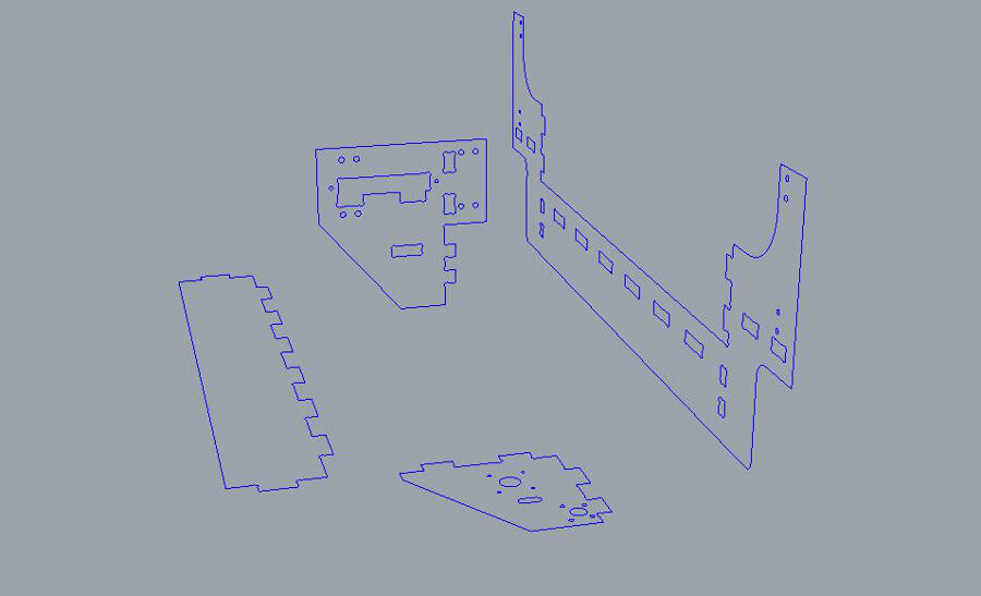
3D file
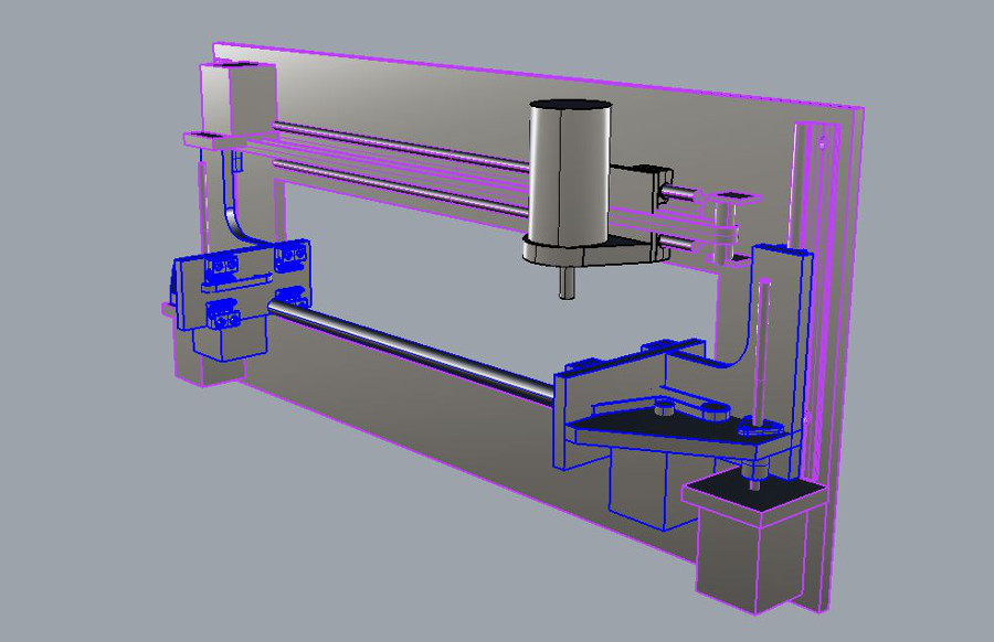
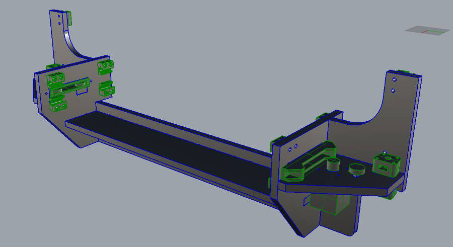
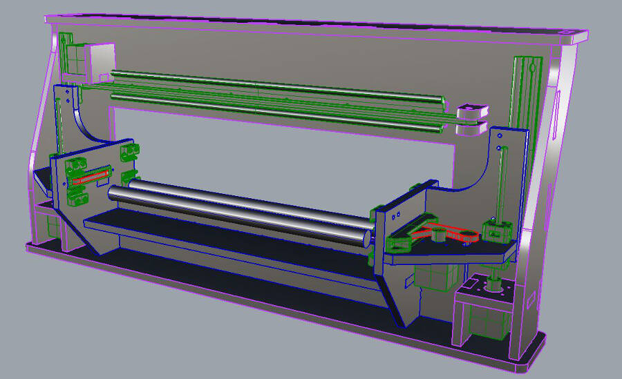
Due to the complexity of the frame I can't design it directly in 2D. Here a screenshot of the 3D version.
How to make a complex file for the CNC machine
I had the problem of designing somethign pretty complex that must consider all the connection with electronic and mechanical componentssome of them, not exhisting yet. I used Rhinoceros 3D, but the technique works pretty well with other software as well.
Here how i did it, hoping to be useful for others in my same situation.
Start from a simple 3D file
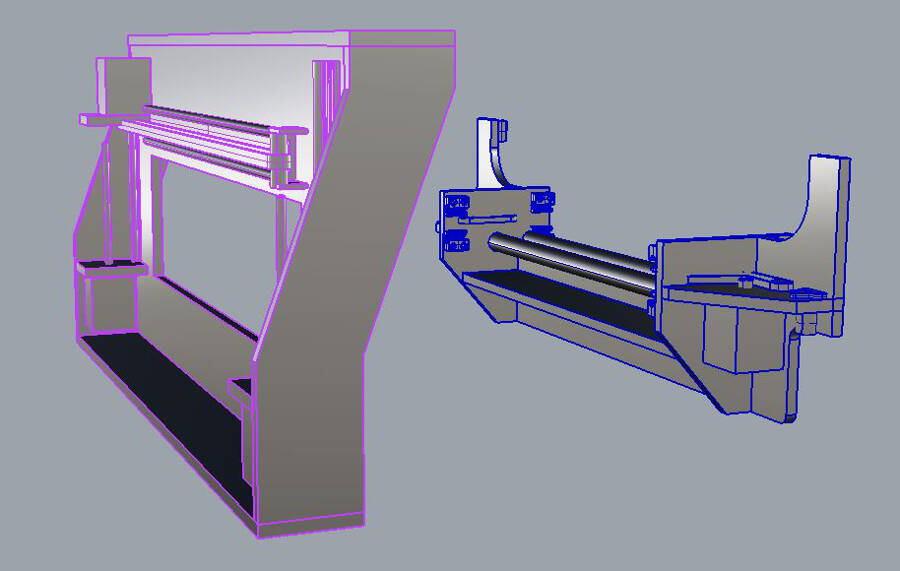
The firs step was to make a simple 3D description of the frame, divided into the functional units
Add all the feature to the pieces
One by one you take all the profile of the pieces and design the features needed, like holes, pockets and joints.
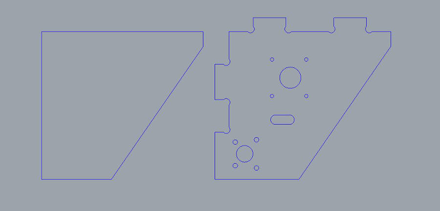
Extrude and put back the edited profiles
After the previous step, you should have a more precise idea of the pieces and the features needed. Extrude the curves and place the piece back in position.
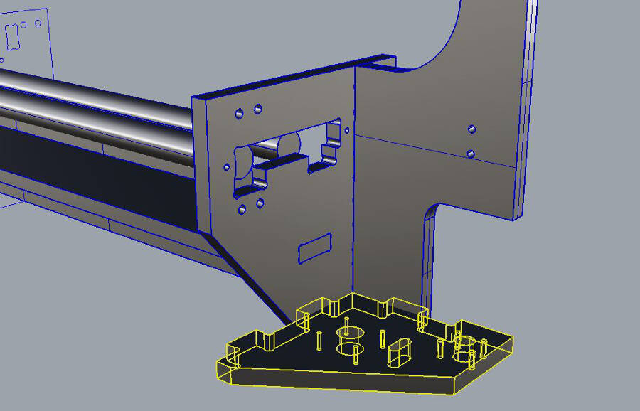
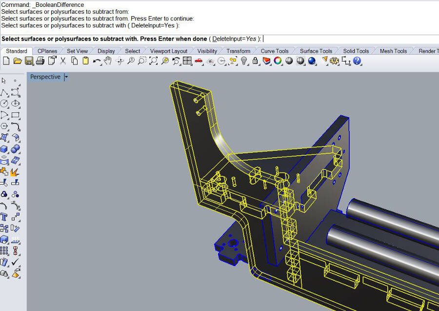
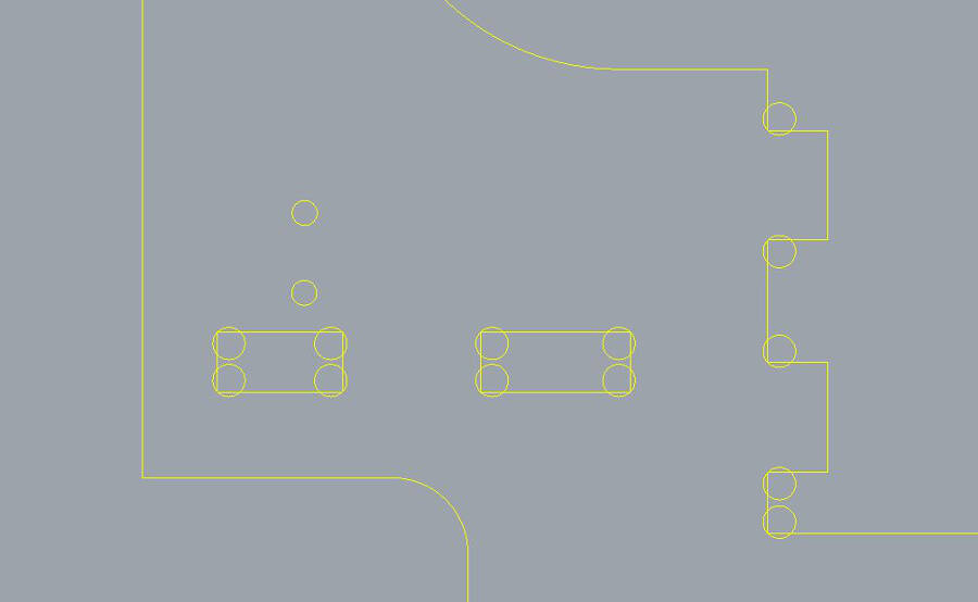
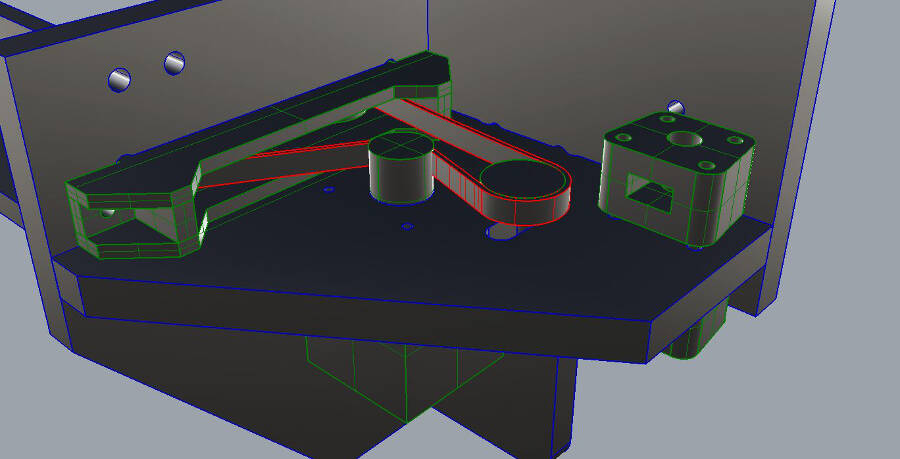
Copy the profile and make a boolean difference
To be sure the joints match, the easier way is to do a boolean difference. This gives you a precise feedback of the position. Here an exemple:
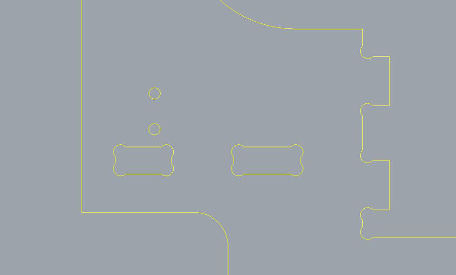
Refine the curves
To properly fit together it's important to don't forget the round divots to make room for the other piece's corner. To reduce the visibility of the divot without make it too weak i use a diameter 0.5mm bigger that the mill end and i make the corner of the cut touch the circle. I tried to use the exact same diameter, but it' pretty risky in ithis case: if the dxf you export is not very precise, i happens that the software is considering the cut too small to do.
Repeat the operation for all the pieces
What's shown for the first profile must be done for all the pieces. Obviously identical pieces and (sometime)simmetrical pieces con be designed just once.
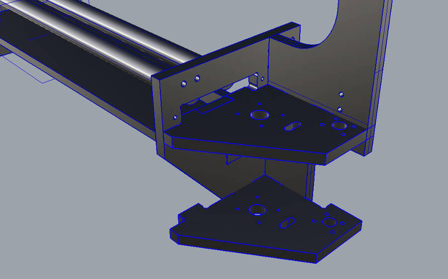
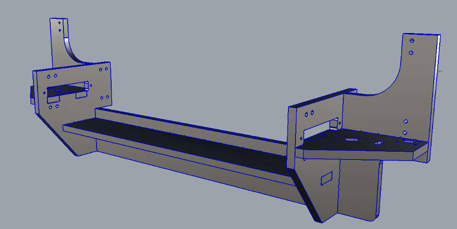
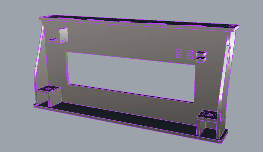
Assemble the 3D files
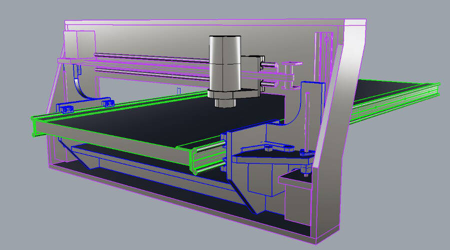
After you extruded the profiles to make the 3D parts, it's good to assemble the pieces together to check for mistakes, interferences, and improvements. Check first just the connections between the pieces to mill, then add all the other componenets, such as 3D printed parts, elctronic and mechanical parts.
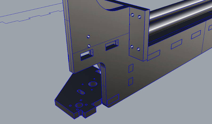
Repeat the assembly for other functional part and for the final object
Just follow the previews steps to assemble and check all the functional units and the final assembly. When you get to a complete 3D version, you can use it to edit the profiles (adding holes, cuts, etc.), measure distances, etc.
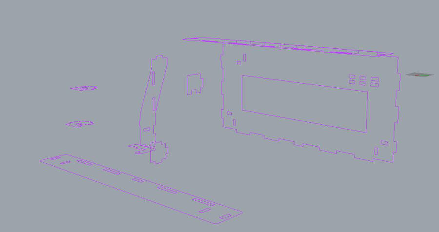
here the cutting file
Tutorial
Here the tutorial I use during the fablab courses and in University.
Setting, cutting and assembling
The frame is cut on a 12 millimeter plywood. The first test was done on poplar, the most common plywood used.
 It's cheap, tender and light. Because of long and soft wood fibers, it's pretty common to break it, and ruin the borders. There are a couple of solutions, but they take a longer time. In general up-cut keeps a better finishing on the bottom layer, while down-cut doeas the opposite. Because of this, you can cut the first half of the panel with a down-cut and the last part with a up-cut. Of course it takes more to change the end mill. As an alternative, you can set the first layer depth to 1mm and cut just the top layer of the plywood. In this case the stress on the mateial is less intense and the wood usually resists pretty well. Of course it's slower that the normal process but it's faster than the changing the tip.
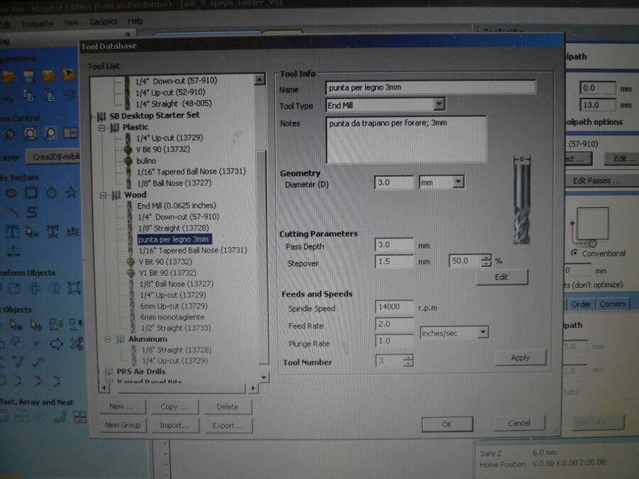
For this tests, I didn't care too much about the finishing. I used two end mill: a 3mm drill for the holes and a 6mm end mill for pockets, profiles, etc.
Here the parameters for the holes with 3mm
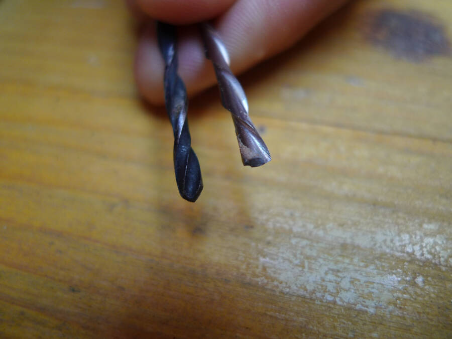
 The best end mill in this case is a normal drill tip. In this picture both the drill tip and an end mill. The end mill has a flat end, and even if it's possible to use it in some cases, it vibrate much more with a less round hole. In this case i used the black drill tip.
 Here the parameters for the cut with the 6mm
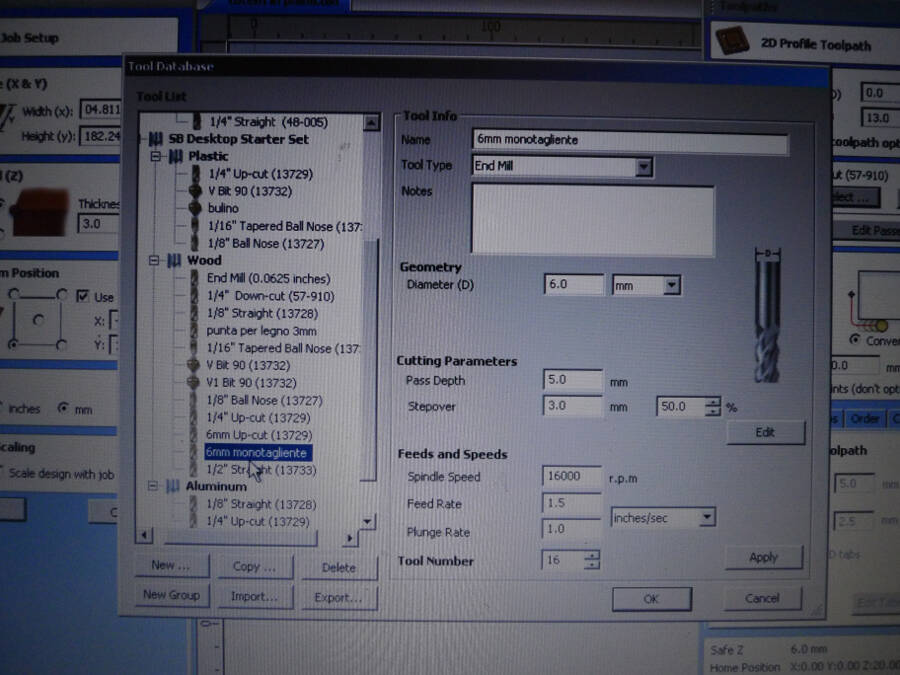 I edited the parameters, being the end mill I used a single blade. These end mills works very well with wood and plywood cause they have a lot of space to extract the wood dust. This allows higher rpm with less vibrations.
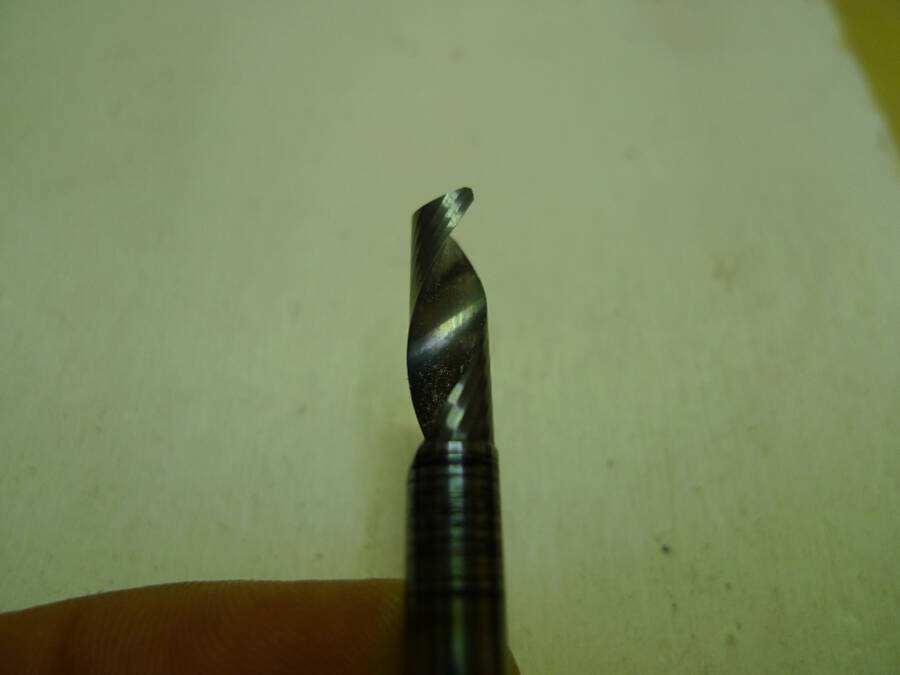
Here the end mill used (to be honest, my favourite)
I edited the parameters, being the end mill I used a single blade. These end mills works very well with wood and plywood cause they have a lot of space to extract the wood dust. This allows higher rpm with less vibrations.
Here the end mill used (to be honest, my favourite)
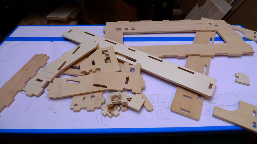
 All the pieces cut are here:
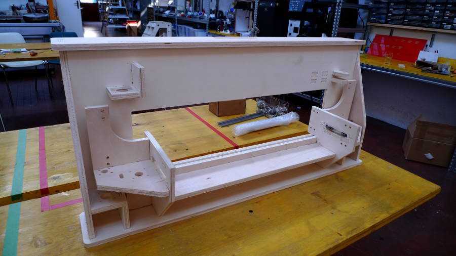
 And the assembled version is here:
 Even if mechanically is not the best solution I used self-tapping screws. I know it's not the best one but it's the quicker for the beta testing.
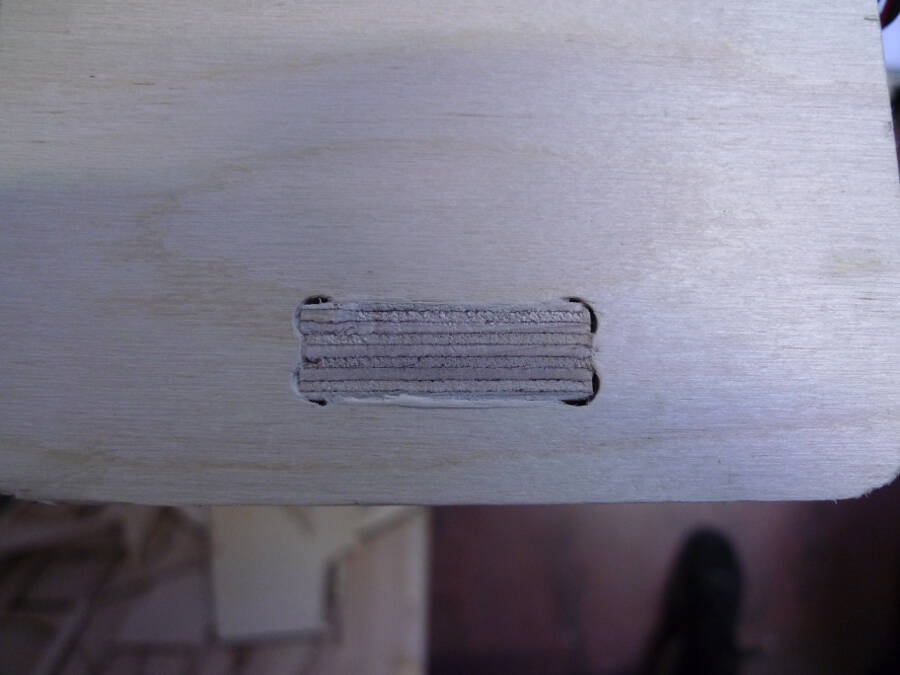
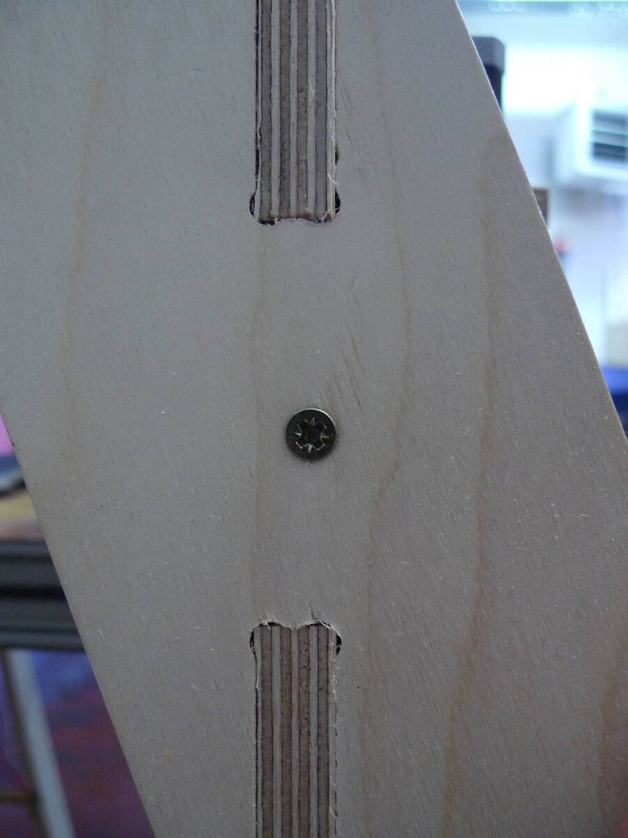 Designing the divots the way shown bofore, the gap is barely visible
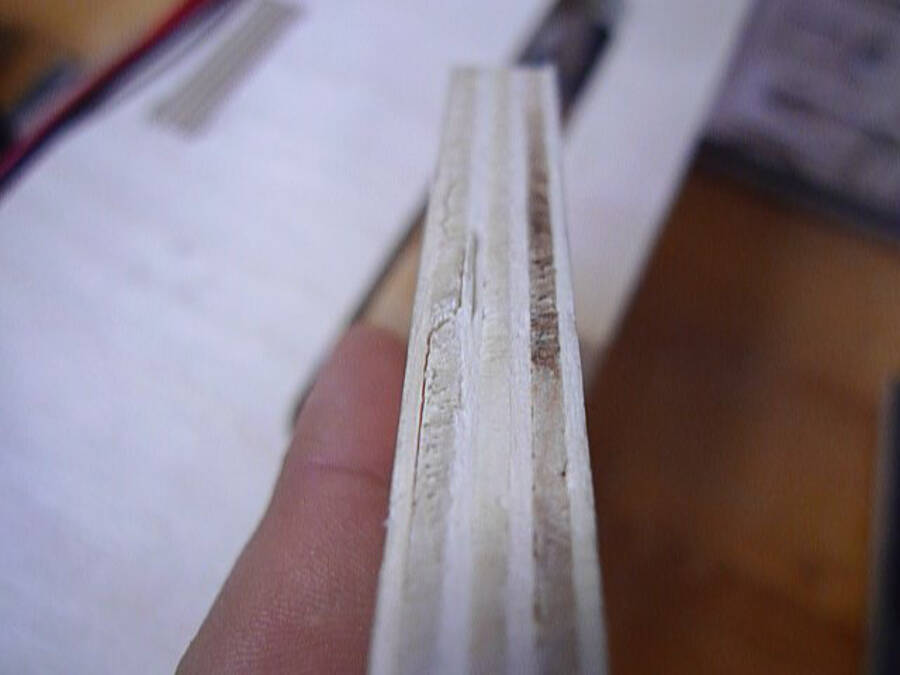
Possible difects
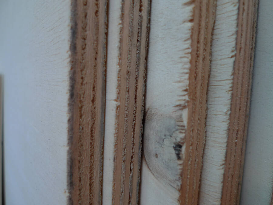
I used two different woods for the two versions of the frame. The first test was done with popler, to work with something easy to fix by hand and to modify. This is one of the most commont problems. The stress generated by the cut is separating the layers.
 For the second version, I used birch plywood. Being a more resistant materialit was good to test the mechanical resistance and the reliability of the frame.
Of course it was harder to cut and the vibration on the piece were pretty strong. I noticed this on the border of a piece with not enough tabs
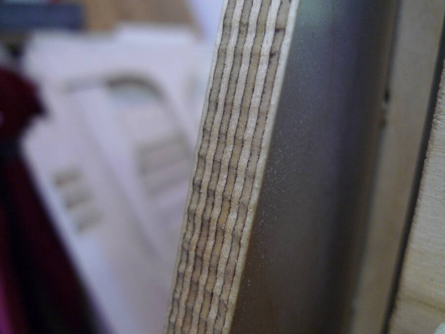 It is probably a consequence of the vibration generated by the cut process. With more and more resistant tabs it's probably gonna be much better.