C o n t a c t F a c e b o o k S k y p e I n s t a g r a m P i n t e r e s t H o m e
14. Mechanical and machine design
Do the mechanical design for your final project
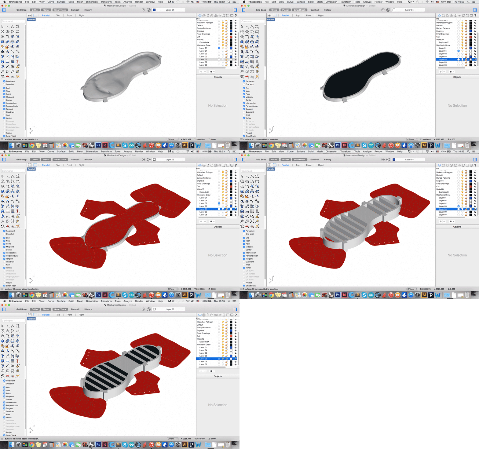
For this week, we are required to create a mechanical design for the final project--but because my project is not 'mechanical' in nature, I've provided diagrams of the physical configuration of the project.
The first diagram shows the layout of the circuitry, which is placed in place after the casting process. Because of the difficulty of casting the electronics in place due to the components rising to the surface, I've resorted to placing the force sensors directly onto the sole of the shoe. Then a thin layer of silicone is brushed on to secure the force sensors in place. The milled boards, lithium ion battery, and switch are embedded within the textile before casting and are soldered directly to the force sensors.
The second diagram below explains the fabrication process and outlines the casting process. The casting process is composed of a two-part 3d printed mold, silicone and a chosen textile. The process requires that mold with the foot relief be cast first with silicone, then the textile be placed on top of that cast and finally, the top part of the mold is secured onto the composite with clamps. The rest of the silicone is poured into place and left to dry.
Download the corresponding files here.


