C o n t a c t F a c e b o o k S k y p e I n s t a g r a m P i n t e r e s t H o m e
13. Network and communications
Design and build a wired and/or wireless network connecting at least two nodes
For this week, I planned to first make the hello.bus asynchronous example in order to understand how it works and then if time allowed, I was hoping to attempt another network setup. Unfortunately, time ran out, but the hello.bus example was sufficient in understanding network communication.
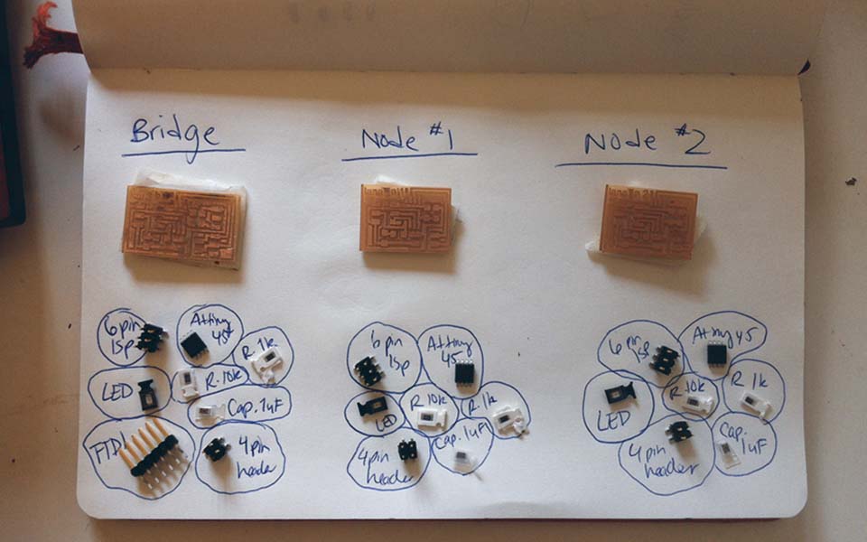
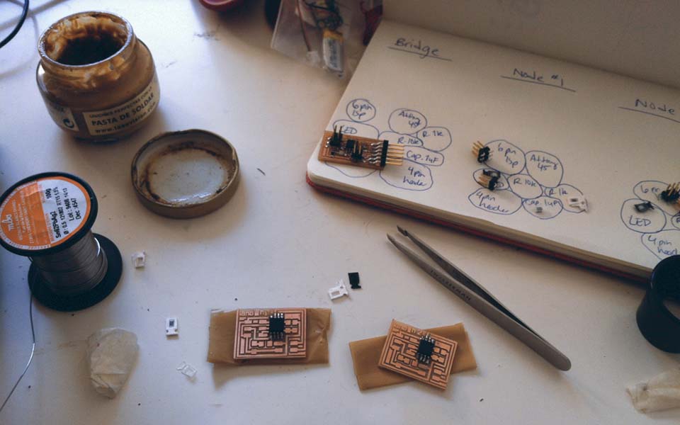
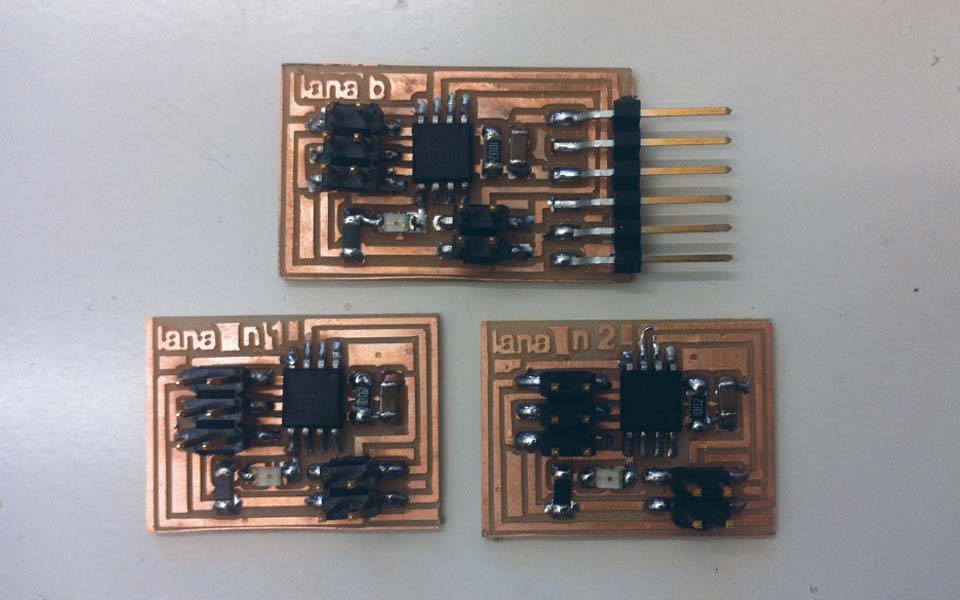
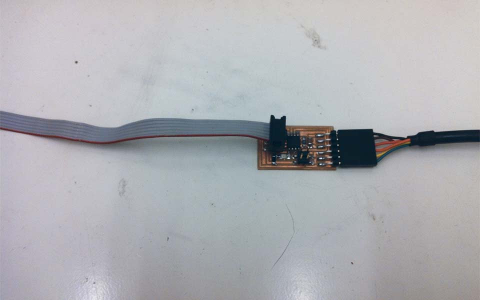
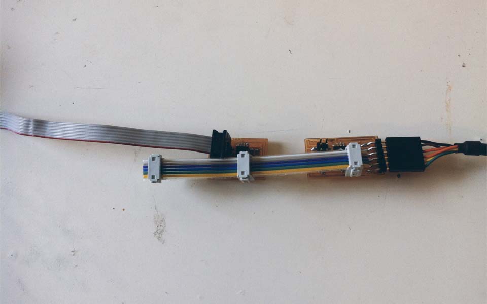
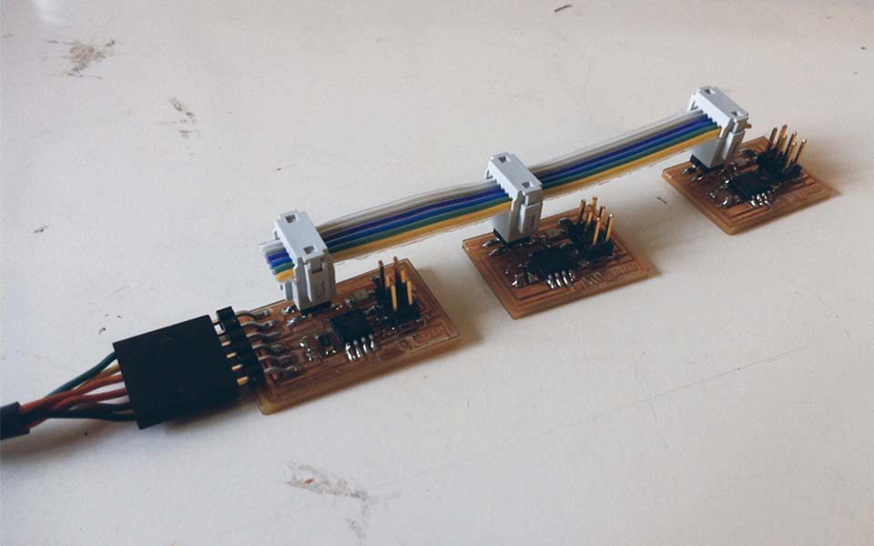
First, I downloaded the files from the MIT CBA class page, added labels and logo, and milled the 3 boards: 1 bridge and 2 nodes. Once milled, the boards were soldered as usual. Details about how to mill and solder boards can be found in week 04. The final boards were quite dirty, but a quick google search resulted in a simple hack: rub it off with a white eraser. Then I washed the residue off with some soap and water and it worked.
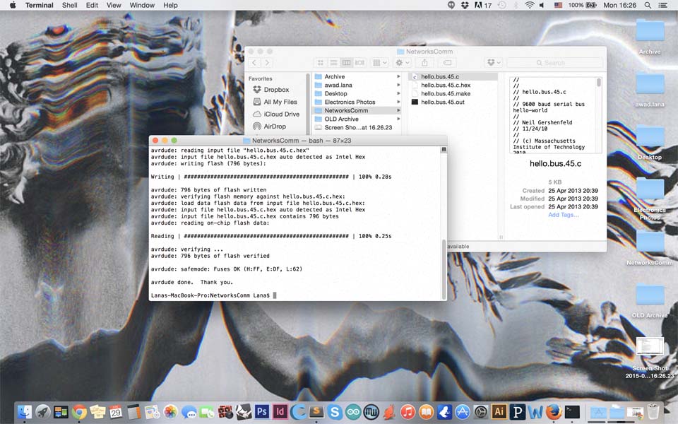
In order to program the boards, I first downloaded the C and Make files into the same folder and ran make -f hello.bus.45.make program-avrisp2 in the terminal. This was the process for the bridge. For NODE1, I changed the hello.bus.45.c code in line 41 to #define node_id '1', connected NODE1 through ISP, and programed it similarly through the terminal. NODE2 is programmed similarly with the only difference being changing the number of the 'node_id 1' to 2 and connecting the ISP to NODE2.
Once all the boards were programmed, the bridge was then connected to USB through the FTDI cable, and the nodes were bridged in sequence. In Arduino, the board and processor was set to Attiny45 with 8MhZ internal clock. Finally, within the serial monitor, depending on which node number is entered, the LED is programmed to blink twice, as seen below. Hint: be sure to set the baud rate to 9600!