Networking & Communications
Assignment
design and build a wired &/or wireless network connecting at least two processors academy.cba.mit.edu
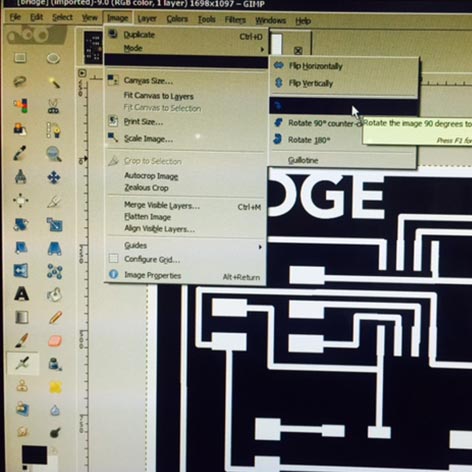
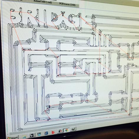
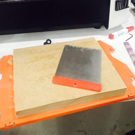
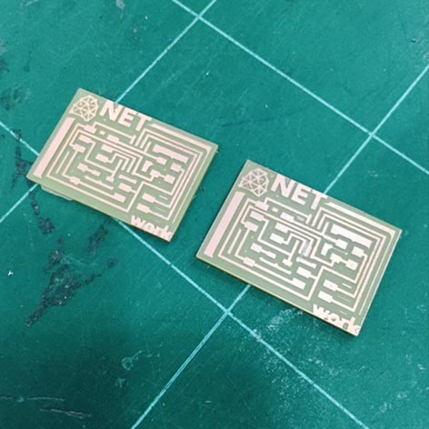
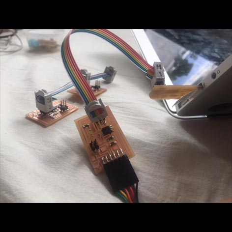
First I designed the schematics in eagle & exported the png into gimp where I added NET to the node boards & BRIDGE to the bridge board. Then I milled the PCBs in the Roland Modela SRM20.
Then soldered all the components to the board. Changed the PCB board from the milling machine to make the network boards & then finished soldering the boards.
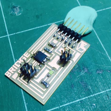
Everything ready to program! Created the cables to be able to connect the Bridge & Node boards as well as the FABISP.

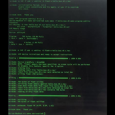
Runned the make file & had a problem with the connection of the FabISP. I checked in the mac system information and was able to find the usb device connected!
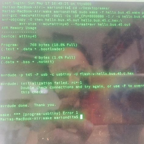
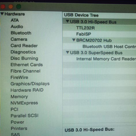
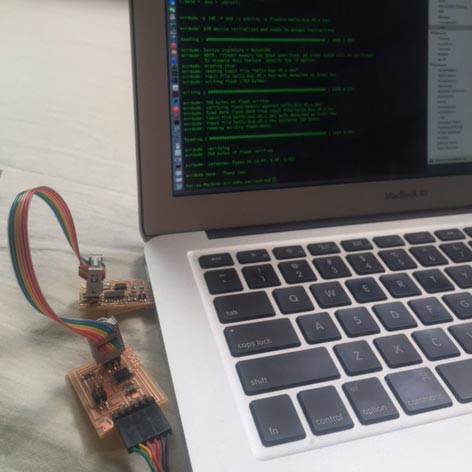
Then ran again the make file (sudo make -f hello.bus.45.make program-usbtiny) and everything was ok! Connected all the nodes to the bridge & runned the programmer one changing in Neil's file the ID number.
Node 1, changed hello.bus.45.c line from #define node_id '0' to #define node_id '1'
saved, and ran sudo make -f hello.bus.45.make program-usbtiny
Then the same operation for node 2: hello.bus.45.c line 41 from #define node_id '1' to #define node_id '2'
save and run sudo make -f hello.bus.45.make program-usbtiny
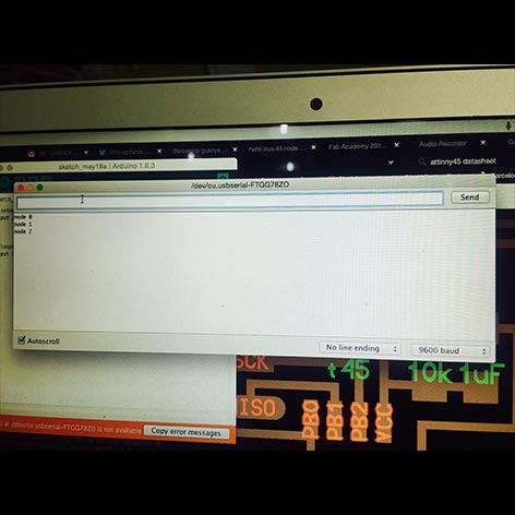
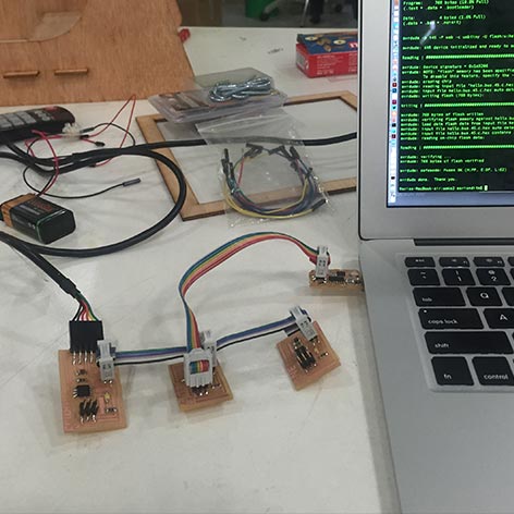
Once all the boards were programmed I proceded to pass the values with the Arduino serial monitor but there was an issue were all the lights would light up instead of communicating... Finally it was due to the baud which was on the wrong rate. The network is working properly! (check out the video)