Input Devices
Assignment
measure something: add a sensor to a microcontroller board that you've designed and read it academy.cba.mit.edu
For this assignment I choose to do the step response - proximity sensor to get an input when people would approach my final project (the bamboo robot). When you get close a speaker will output a sound.

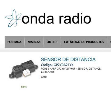
For this first step I will only add the proximity sensor (Sharp GP2Y0A21YK) which I found at the local Onda Radio store. There is another local store called Diotronic as well which has a very wide inventory.


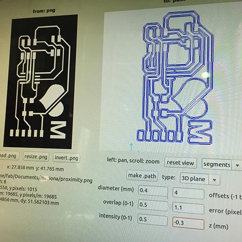
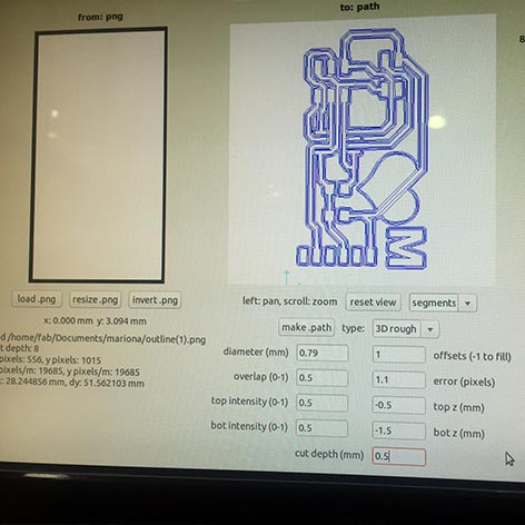
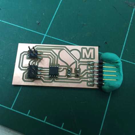
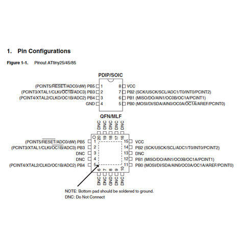
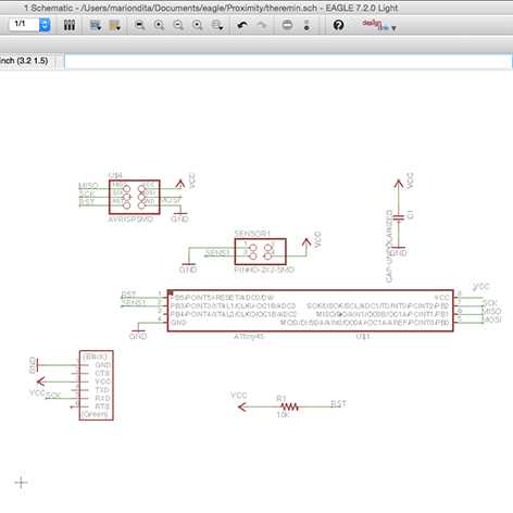
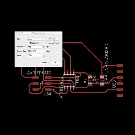
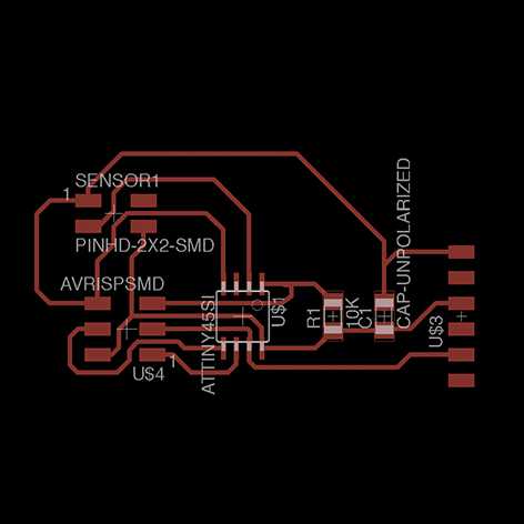
Download the attiny45 specs & proximity sensor to check where to solder the GDN & VCC as well as to where to add the cables in the pin connector FCI 6 pins.

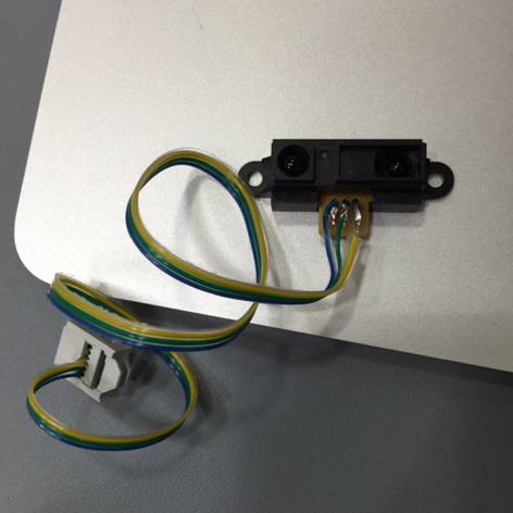
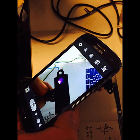
Using a phone to check if the laser works
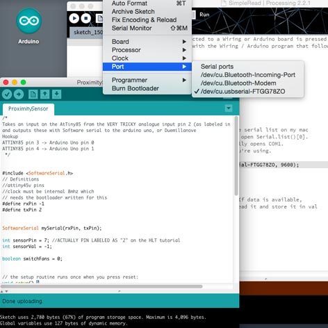
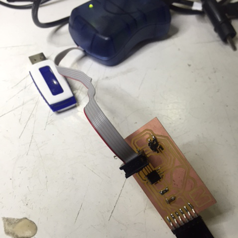
The proximity sensor programmed with Arduino works perfectly! Here is the Arduino Sketch.
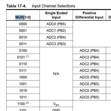
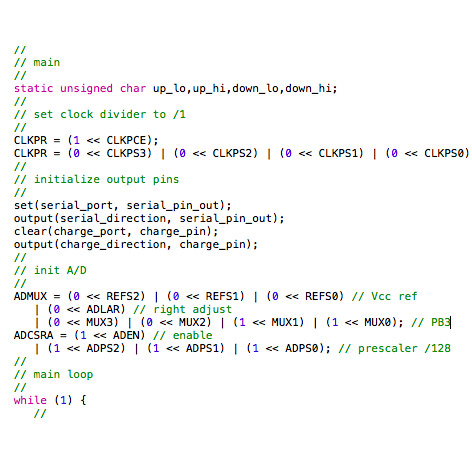
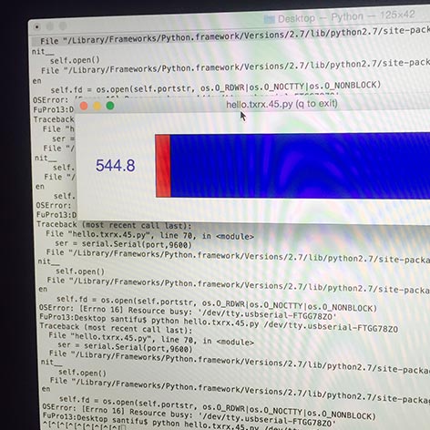
Next step is to get the same effect with C & display it via Python web interface. To accomplish it download the attiny45 load make file from the step response section (in this case it will be programmed to detect proximity) & the C file. Then I checked the attiny45 datasheet to check for the pin values & added the value PB3 - 0011 MXU values to the C file. The last step is to add the python file in order to be able to display the values read by the Sharp proximity sensor.