Table of contents
- The concept
- Picking the right cardboard
- Analysing the design files
- Lasercutting the cardboard
- Assembling the first stage
- Refining the design files
- Picking the right cardboard 2.0
- Assembling the first stage 2.0
- Milling and soldering FabNet
- The power supply
- Hooking the first node
- Single_node.py test
- Understanding single_node.py
- Connecting two stages together
- Building machine's frame
- Hooking the two nodes
- xy_plotter.py test
The concept
This page is meant to document all the steps throughout the group week of the machine building weeks.
The assignment was to building a machine with Nadya's reconfigurable stages. The main concept is that we can build "almost" any machine reconfiguring the way we assemble the stages. Allowing us to add as many axis as we might need.
Picking the right cardboard
The first thing to do was getting a good quality 4mm thickness cardboard. So we went to some retail spaces and asked them for used cardboard boxes. After some prospection and logistics we ended up with our lab full of cardboard.
Most boxes we collected weren't good enough for our purpose and we were almost getting frustrated for not finding the right cardboard. But after some persistence we found out that the "W5" packaging cardboard from Lidl had the most interesting characteristics so far.

This was our first test. Fine tuning the designs, getting the right cardboard and assembling the first stage to get the idea of how it exactly works.
So we downloaded Nadya's designs, converted the file to mm, and cut them right away, just to understand that there were some extra adjustments we needed to make.
Analysing the design files
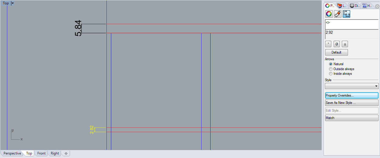
The first file we cut was the machine's head and we identified some dimensional errors, mainly on the thickness of the cardboard. Nadya's page states that the .dxf files were optimized for .15" cardboard (aprox. 3.8mm) but once we measured the drawings we noticed that the designs were actually meant for 2.92mm thickness cardboard...
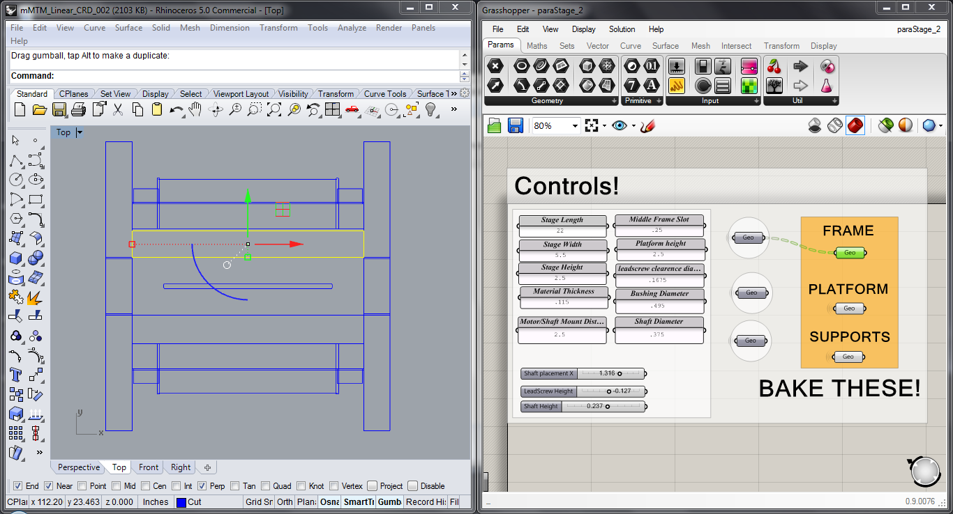
So we decided to use the Grasshopper file to adapt the design to the 4mm thickness. At first it looked like a good idea, but after paying close attention to the definition and baking some of the nodes, we found out that making it manually would be quicker than understanding and rearranging it. The Grasshopper definition needs more maturing in terms of its extension, overcomplexity and final result.
p.s.: The grasshopper file has been updated on the page, so what we're stating here might not be true anymore.
Also, we noticed that the nodes that are supposed to be baked into Rhino are just overlapped rectangles, meaning that after correcting the grasshopper definition we would need to explode the them, delete the overlaps and choose wich lines are for engraving and wich are for cutting.
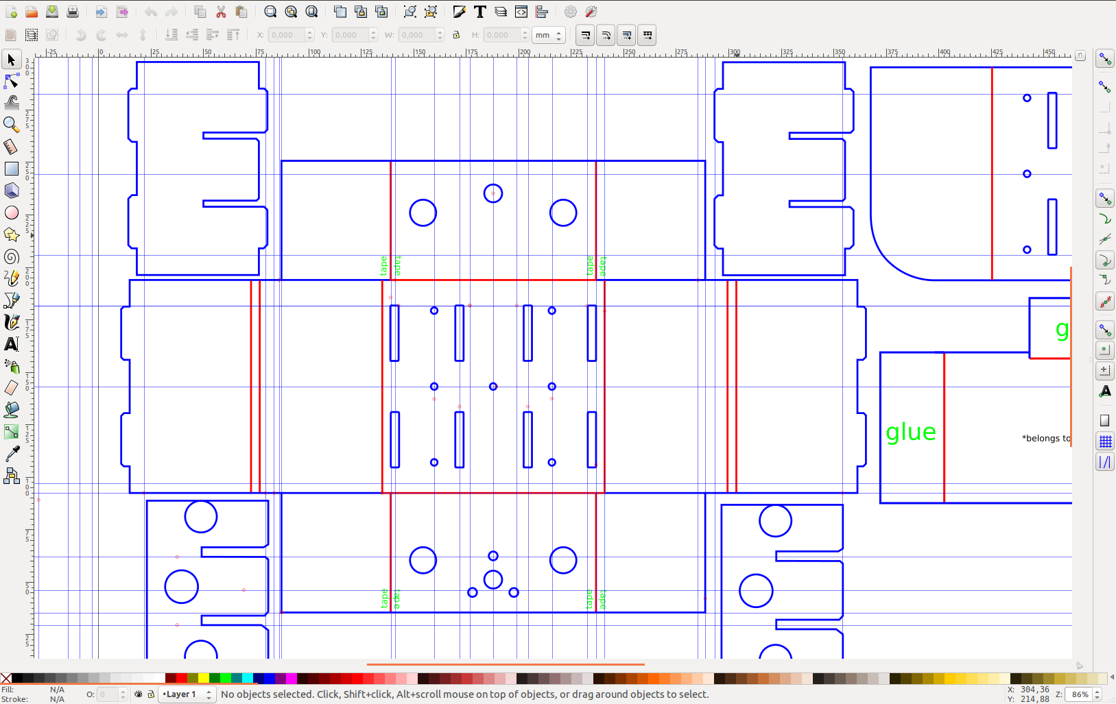
So we decided to go for the .dxf file and refine the drawings on Inkscape.
Making good use of guidelines and snaps on Inkscape let us make the first set of changes to the design. The first set, yes, because, as you'll see further, there were still some nasty errors to unveil.
Lasercutting the cardboard
The best way to understand a design is to reverse engineer and rebuild it. As we already had the files, we just needed to lasercut it and assemble the parts.
We first cutted the board using the following settings:
RGB Red (255, 0, 0) for engraving and RGB blue (0, 0, 255) for cutting.
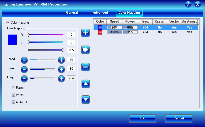
At first we tried to reduce the red line frequency to emulate a dashed line, but it didn't worked the way we expected.
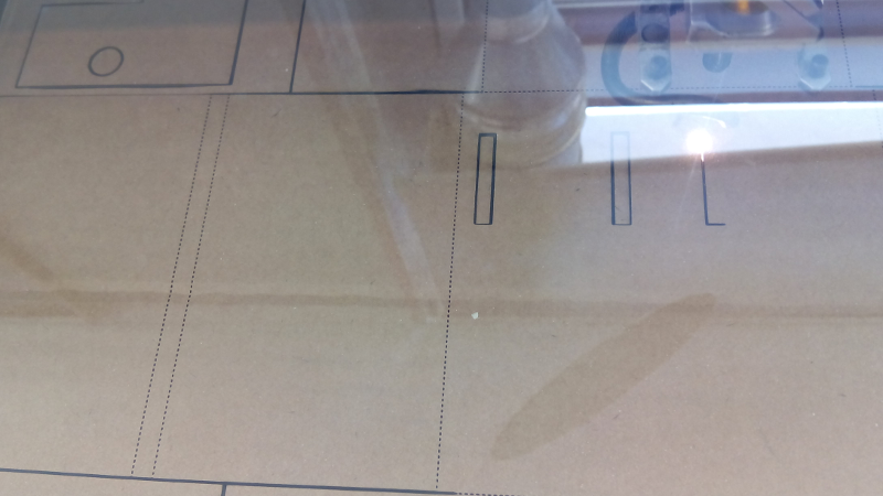
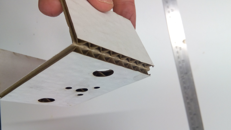
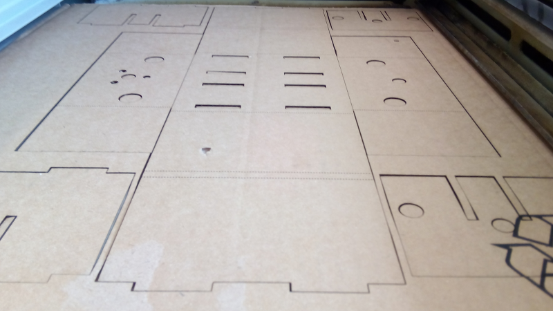
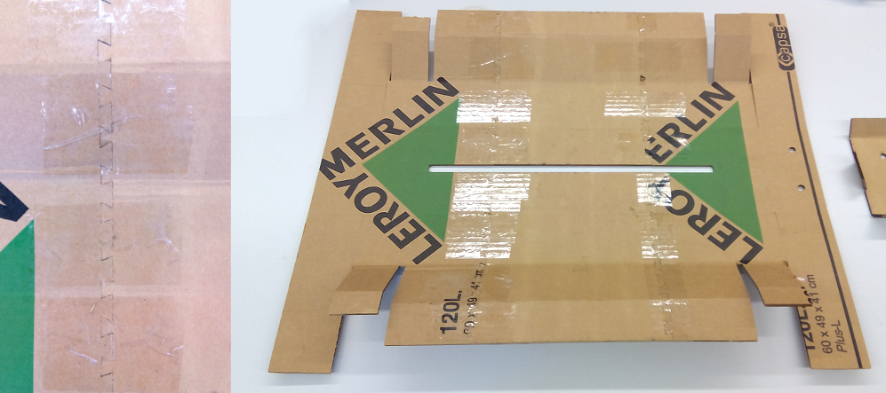
For all the assembly to work correctly the laser needs to cut two layers of card, leaving the last layer to fold, like the image below shows.
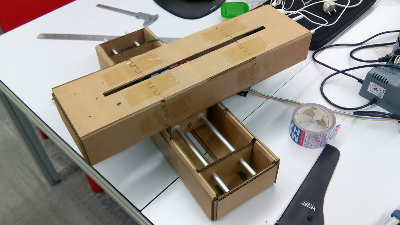
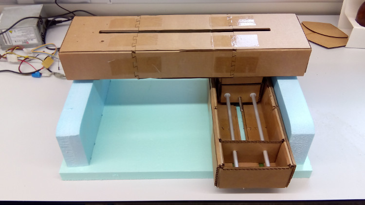
Assembling the first stage
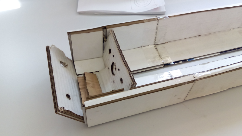
We decided to start assembling the smaller section of the stage. And as you can see from the image it didn't worked at first try.
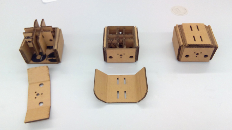
So we did some extra iterations on the design so that everything could fit perfectly.
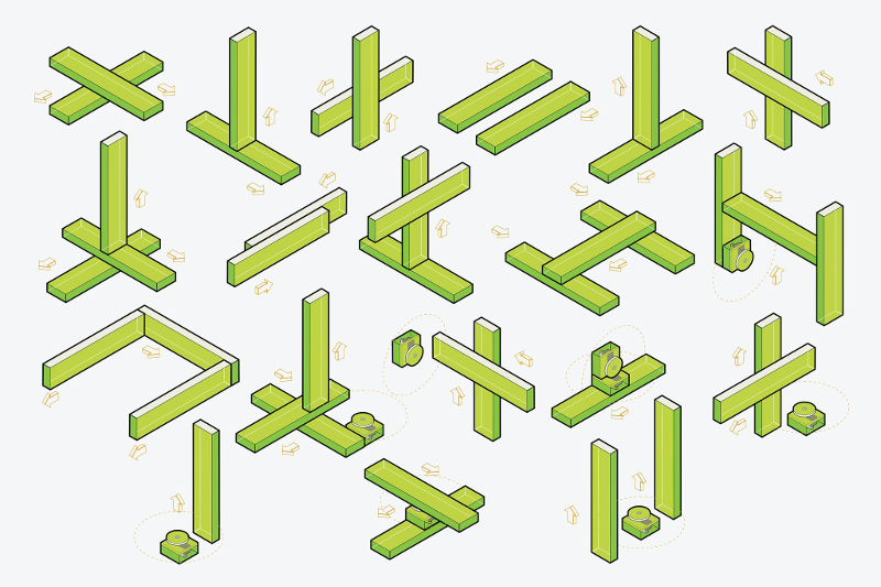
After that we used Nadia's assembly instructions to figure out how to assemble the larger part of the stage. It took a while to understand it from the animated .gif so we decided to separate it back into its original frames using Gimp.
Here you can find the layers as a Gimp file:assembly_steps.xcf
Even though it's still complex, but is more manageable this way.
As we only have a 600x300mm machine, we divided the main body in three parts, using Nadia's joint design.
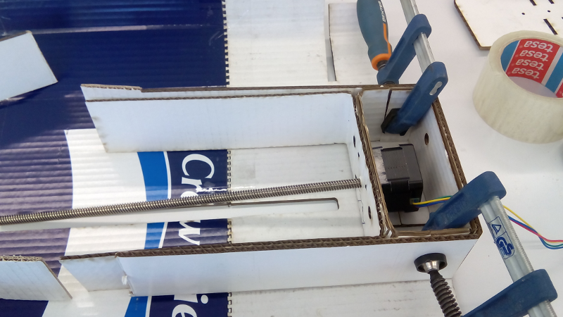
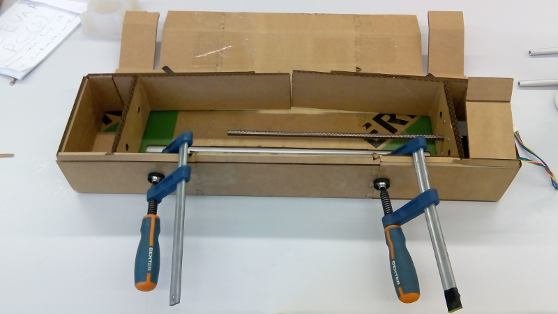
There was also a need to add glue on some side parts of the stage, as documented on Nadia's project. That's why we used the clamps.
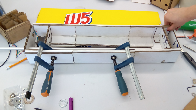
Oh, by the way, always remember to screw the motor before gluing the side parts!
PLEASE LOOK at the image below!!!!
Refining the design files
So, after assembling the first stage, we noticed that there were still some persistent errors on the design. So we took notes on the problems we were encountering during the assembly and went back to the design stage.
 hard times assembling the cardboard
This was the thoughest part. Lot's of coffee and a day spent in front of the pc fine-tuning the last errors.
We also added some extra features to the design. For example, the preferable orientation for the cardboard (black layer on the image), so that the stronger direction of the cardboard can tolerate the applied pressure when assembling.
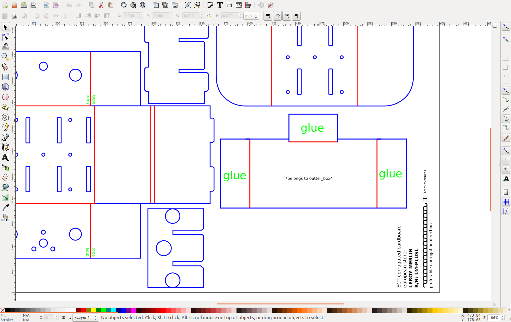
Another interesting feature is the places where you need to add glue or tape. You can even engrave it on the cardboard so you don't forget.
We ended up with 4 files. One for each 600x300mm cardboard.The file names are representative of each part of the stage.
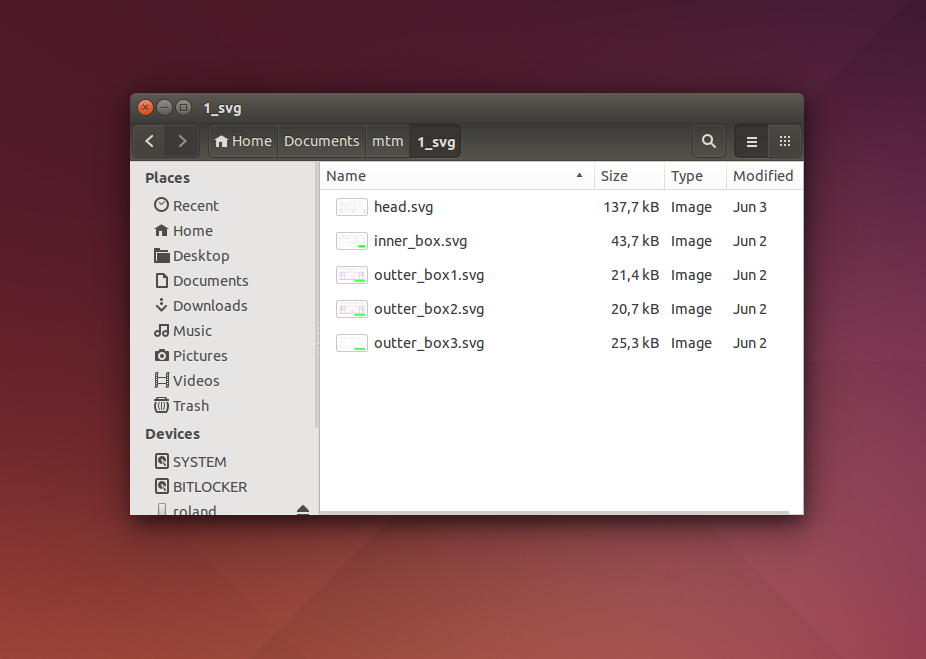 organized files for lasercut
Here are the final drawings for fabricating the stage: stage_designfiles.zip.p.s.: beware, the design files are in milimeters!
Picking the right cardboard 2.0
But the designs weren't the only problem on this stage. The "W5" cardboard we pick was still not great. So we put our hands to work looking for more robust cardboard.
After a quick search on the main bricolage websites we saw nothing with the characteristics we were looking for. So we decided to confirm it locally.
Surprisingly, Leroy Merlin had that rare cardboard with 4mm thickness and Edge Crush Test.
Here's the cardboard reference: LM-PLUSL
We decided to buy it right away. It was a bit expensive, 15 euros for a 40L box, but we needed that cardboard badly to complete the task and Portugal seams to lack good consumer cardboard.
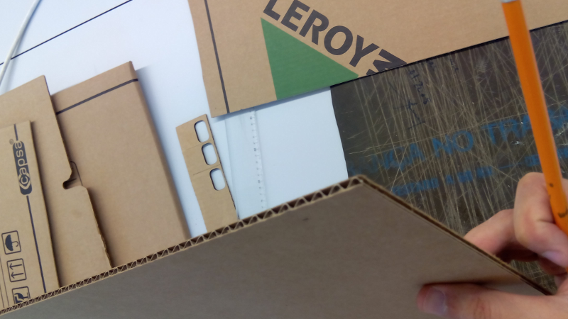 Leroy Merlin good quality cardboard.
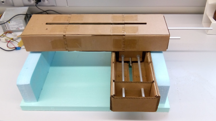
Assembling the first stage 2.0
Now that we have a really nice cardboard and adequate designs, it's time to lasercut the full stage.
So, once again, following Nadia's .gif and our .svg instructions we started assembling the parts.
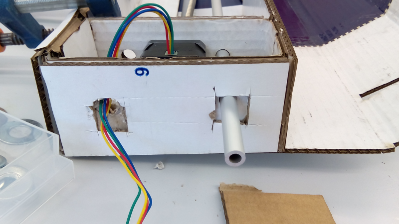
On the image below you can see that we added tape to reinforce the joint section. We also changed the joint design as there was no need to have so many dovetail joints.
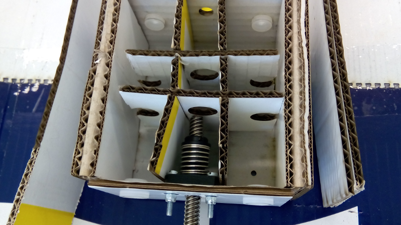
On the images below you can see the places where it needed glue and the motor pre-assembled when gluing the first inner piece.
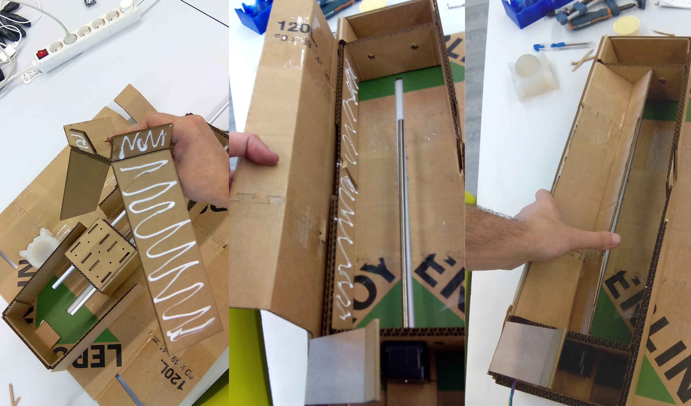
...and then, holding the folded cardboard while the glue dries out.
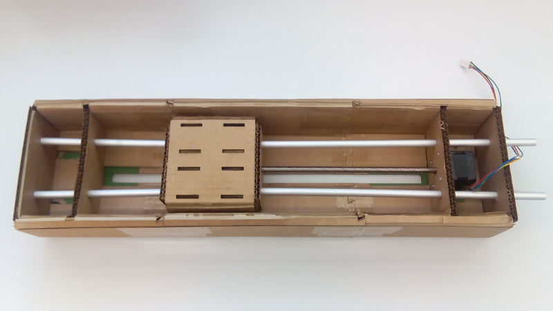
Ater completing this task, we built the head part, screwed it into place and with a blink of an eye we assembled the stage.
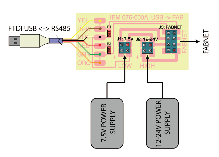
Milling and soldering FabNet
The FabNet is a small circuit with two very important tasks:
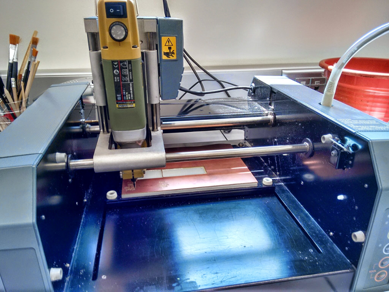
After correctly analysing the circuit, we downloaded the png file and milled it directly using FabModules Online and Modela MDX-20.
If you want to know more about how to run Fabmodules online correctly follow this link. They have a good set of instructions: http://open3dge.com/fabmodules/
We used the standard settings for milling PCBs (PCB traces) and changed the tool diameter to 0.4mm, instead of the 1/64 inches as we have a metric mill.
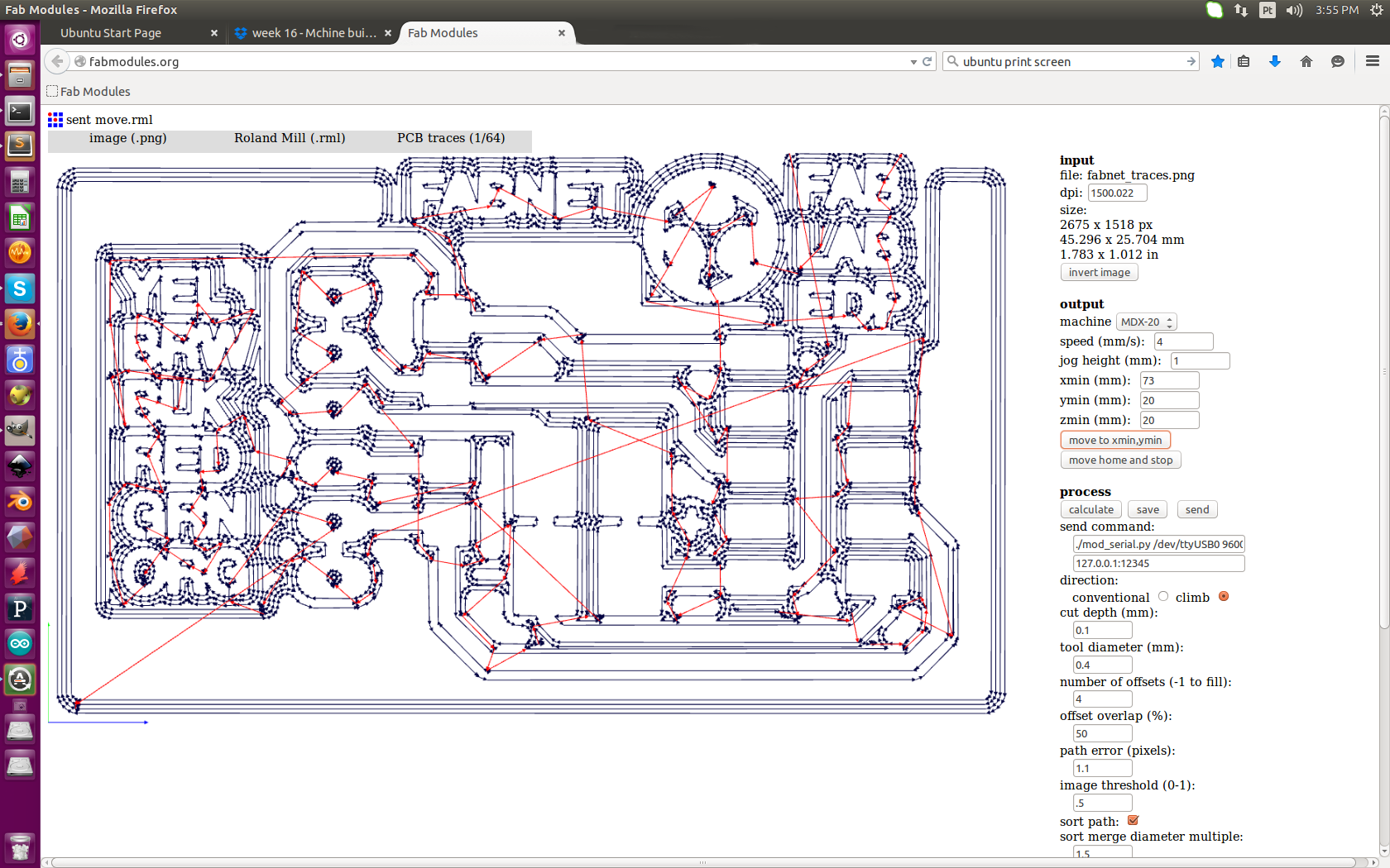
By the way, our Modela is slightly different, although the procedures are the exact same.
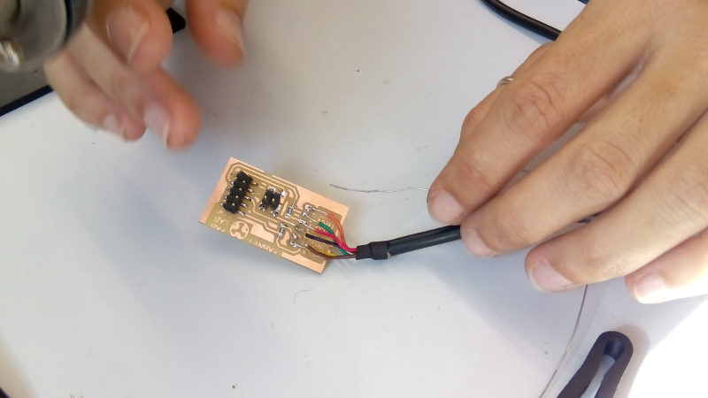
Then we soldered the components as instructed on the board's .png.
The power supply
For powering the machine we started using an old computer power supply.
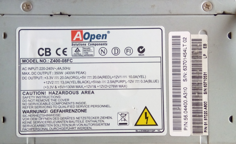
By reading its specs we decided to use the yellow/black cables, meaning 12V - 10A.
Although Nadia's BOM uses a 12V - 5A power supply, this one will work just fine. The circuit will only push the current it needs, so you can feed it with more than 5 amps.The 12V are mainly for feeding the NEMA 17 motors.
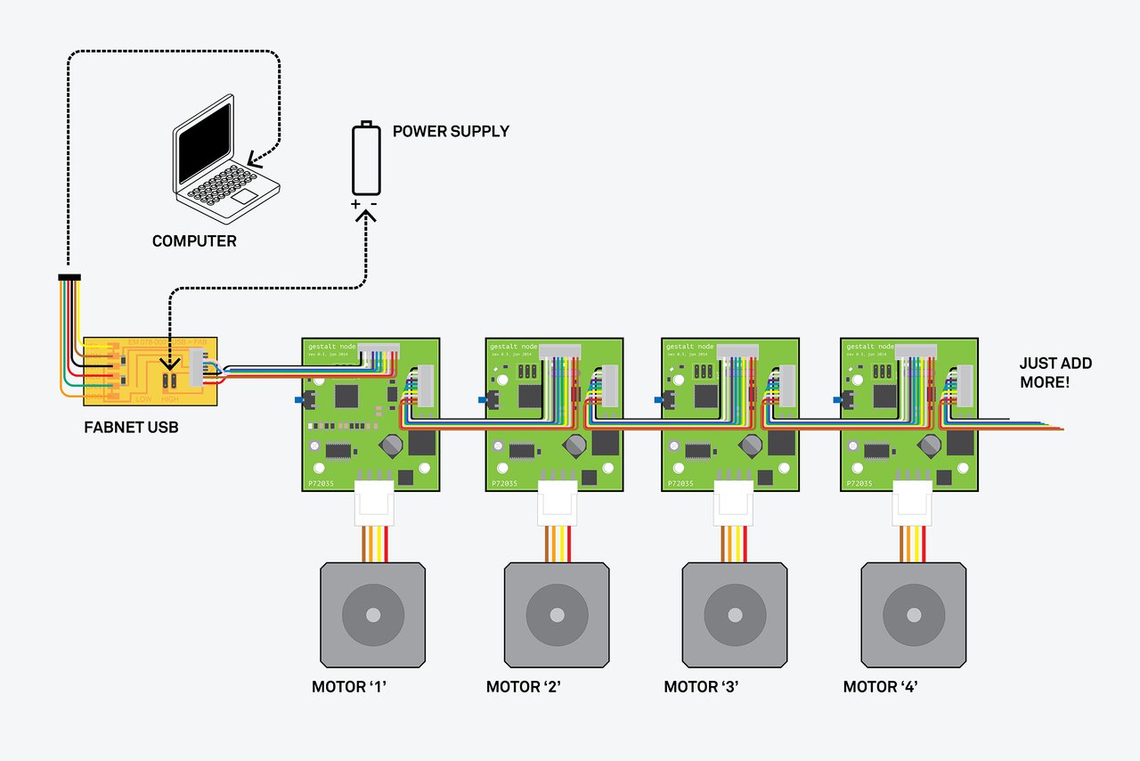
Hooking the first node
For hooking the cables we followed Providence's instructions under the FabAcademy tutorials.
So, we have four components to connect:
The first ones to connect will be the FabNet together with the node. Just follow the image correspondence.
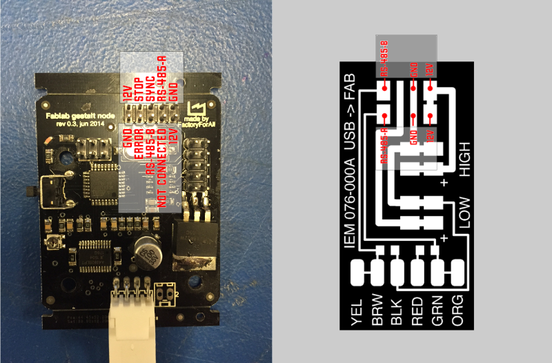
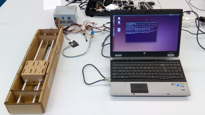
Then we connected the power supply 12V - 10A cables to the Fabnet board.
We plugged the USB to a computer running Ubuntu 14.04LTS.
DON'T HOT PLUG the nodes! They are not protected!
Single_node.py test
Now that all the physical structure is ready, it's time to test it with some code.
Nadia uses a python "framework for virtual machine control of automated tools" called Gestalt.
As we were using Ubuntu 14.04LTS, Python and its dependencies were already met, so we just needed to download pygestalt from github.
sudo wget https://github.com/nadya/pygestalt/archive/master.zip -P /opt/
cd /opt/
sudo unzip master.zip
sudo rm master.zip
Then we extracted its content and ran the Python setup.
cd pygestalt-master
sudo python ./setup.py install
With everything installed its time to see if the motor works as expected. For doing that, Nadia left a file called single_node.py on pygestalt where we can output some coordinates for the stage.
cd example/machines/htmaa
python single_node.py
Once we ran the program, the terminal prompted us with a couple of messages.
The first one was:
IOError: [Errno 13] Permission denied: 'motionPlannerDebugFile.txt'
This is a simple permissions error, wich means we have to run the program as super user, so it can read, in this case, the file "motionPlannerDebugFile.txt". So...
sudo python single_node.py
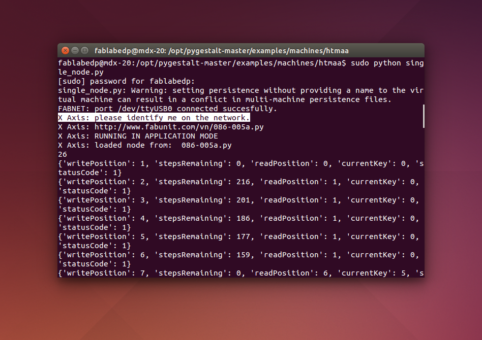
After running the command, the terminal output some other message:
single_node.py: Warning: setting persistence without providing a name to the virtual machine can result in a conflict in multi-machine persistence files.
We are still trying to figure out how to solve this error, although there is nothing to worry about this message.
Then the computer successfully connects to the node on ttyUSB0 port:
FABNET: port /dev/ttyUSB0 connected succesfully.
and prompts you to identify the node on the network:
X Axis: please identify me on the network.
Confirm that the pink led on the board is blinking and press the button once. Like shown on the following video.
Then the program will recognize the stage and sends the movement instructions from the code to the machine.
Now your stage should do some crazy dance back and forth.
Hehe first victory!
If you still have problems, please keep reading...
Understanding Single_node.py
After the first test we decided to look into the code and understand what's under the hood.
sudo sublime single_node.py
In our case we used Sublime text to view the text code, but you can use other programs like Gedit already pre-installed on your Ubuntu system.
Right at the beginning of the code, on the comments, there are two important parameters to set: the portname and the firmware hex file.
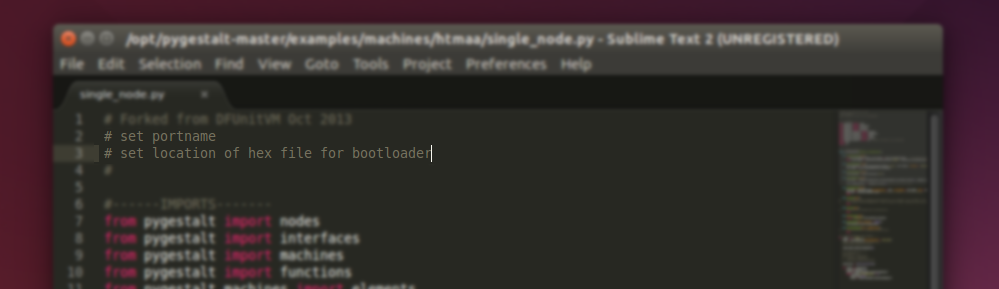
Well, the first one is easy to solve, as we already loaded the code to the node and everything worked ok. The node has been recognized on the port. So, no changes to be made on our side.
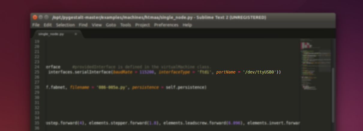
But if the program is not finding the port on your computer, probably its because Ubuntu might not assigned ttyUSB0 as a portname for your FTDI cable. So you can find it by typing ls /dev and look for another ttyUSB, probably ttyUSB1.
Then change the portname on the single_node.py file.
The second comment is a bit more complicated to solve as the firmware has already came pre-loaded on the boards, so we don't have the hex file.
As a solution we downloaded the firmware from Imoyer's Github and used its hex file.
p.s.: We assume that the firmware was loaded onto the boards using an AVRisp as stated on M-MTM's page, so this hex file doesn't need to be changed.
Also, we want to thanks you Koomen Casper for the great documentation and findings.
So, after the download, we extracted the firmware to the Desktop and copied the 086-005a.hex file to the single_node.py directory.
cp ~/Desktop/086-005-master/086-005a.hex /opt/pygestalt-master/examples/machines/htmaa/
Then we went back to the single_node.py file on sublime and uncommented the following line:
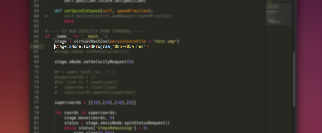
The last thing to notice on single_node.py are the supercoords. these are the movement coordinates for the machine movement. We tested the supercoords by changing its values and reloading the program.
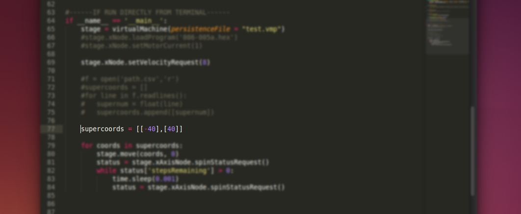
On this case we are testing a positive and a negative value.
From the tests we understood two things:
- with positive numbers the head moves towards the motor, with negatives the head goes away from the motor,
- the following coordinates are always relative to the first coordinate.
As an example if you want to go forward 40 steps and go back the startup place you should type:
supercoords = [[-40],[0]]
Connecting two stages together
With the first stages working properly, we started building the second one using the same refined design files.
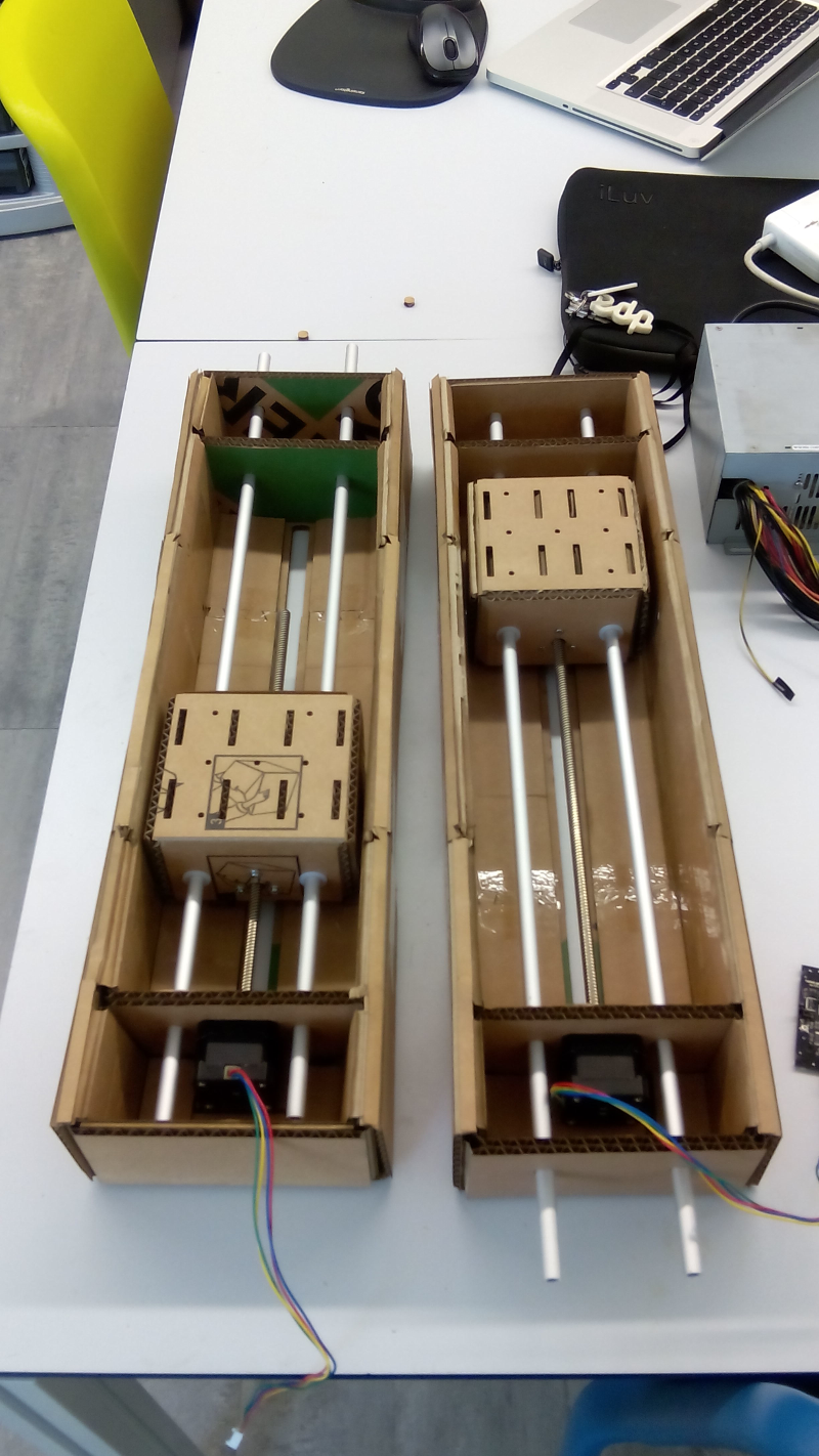
This time assembling the stage was faster as we learnt how to do it from our previous atempts. In less than 30 minutes the stage was ready.
Then we discussed different ways to connect the stages.
The easiest and most reliable way to do it with not much time left was to use cable ties, as Nadia did, and add some mdf boards in the middle to give greater resistance and stability between both parts.
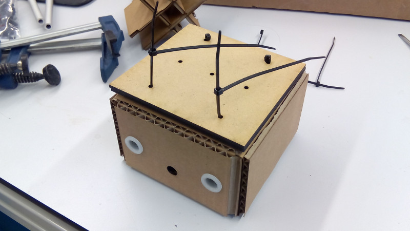
Putting these tiny cable ties in place was a bit tricky because we needed to add more of them together to complete the desired lenght and decide the exact number of cable ties per side.
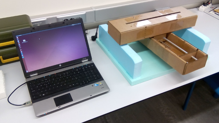
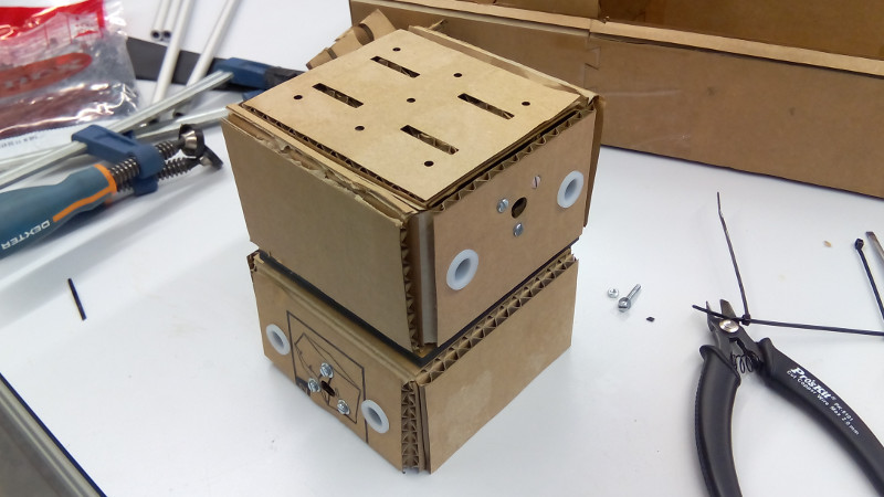
Now, with the heads inplace it was time build a nice frame for holding the stages.
Building machine's frame
For building a frame for this machine, there were no tutorials and we had to depend on our own skills and creativity to design one.
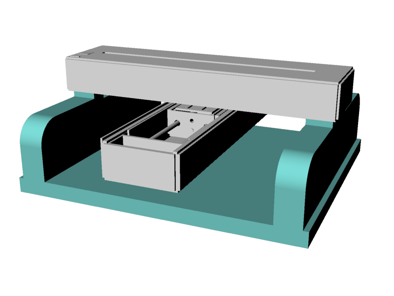
After some debate, we decided to go for the layout as show on the image above.
Two volumes holding the sides of the upper stage, all connected to a flat board working as a base and buildplate.
At the same time we were thiking about materiality. As this is a cardboar machine, should we use heavier materials like plywood or MDF as a frame?
We came into a conclusion that those materials don't talk the same language. So we thought out of the box for a CHEAP, LIGHT and STRUCTURAL material that we could have at the lab.
After a while we saw a large pile of roofmate and we immediately decided that this would be the best material for our frame.
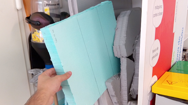
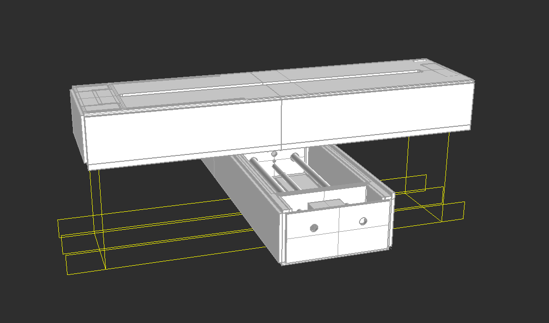
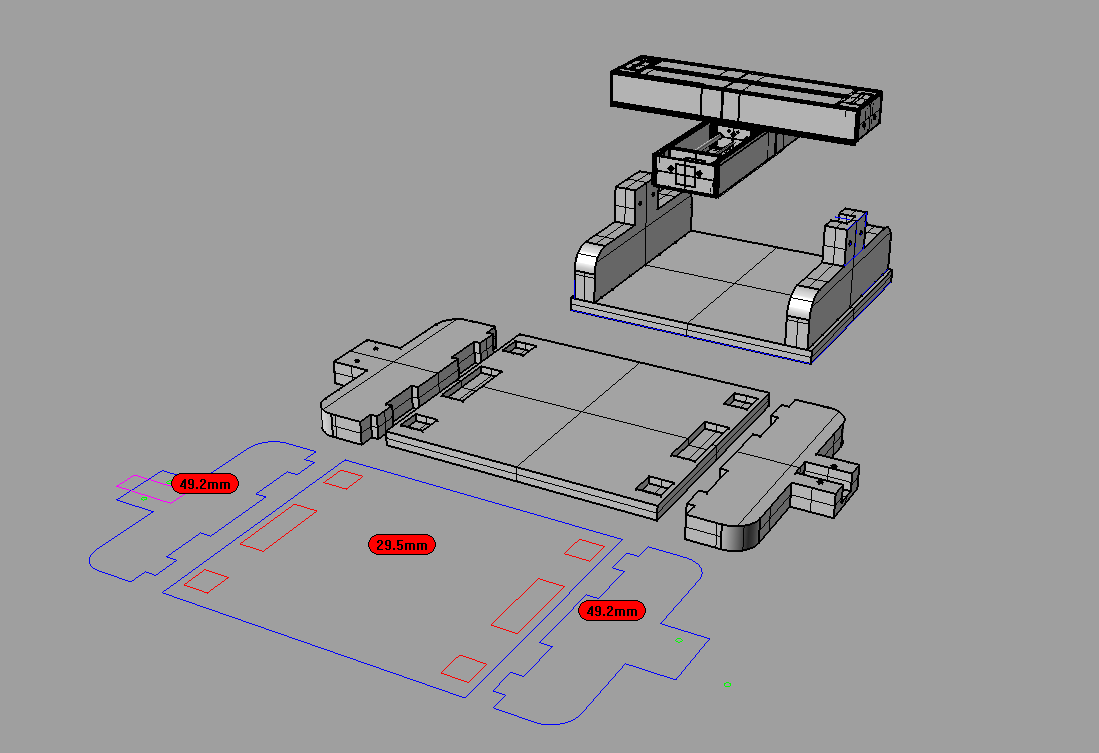
We picked two different thicknesses of roofmate 49.2mm and 29.5mm and with that in mind we went to Rhino, and used as a scale reference, Nadia's 3d model of the stage.
After some sketches we ended up with the following design.
With it we were able to avoid glue and screws and reduce the machining time to the minimum as there are only three very simple faces to cut.
Here are the Rhino frame design files.
and the .dxf design files.p.s.: beware, both design files are in milimeters!
Now it's time for machining the frame.
We used a large endmill with a generous cutting height so we were able to mill fast and deep. These were the settings used:
- tool: 6mm endmill
- passdepth: 20mm
- stepover (where applicable): 80%
- feed speed: 400mm/s
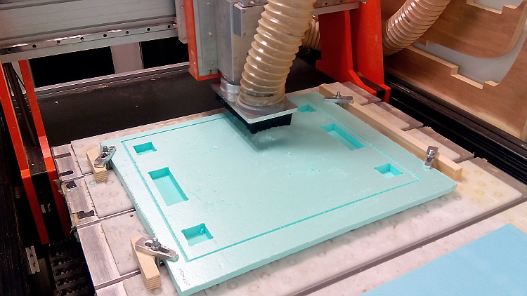
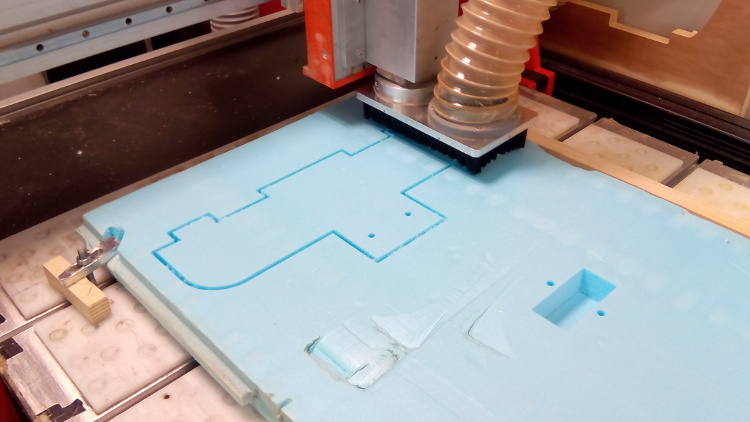
With the milling complete we cut the tabs and assembled the structure together.
step 1: put the stage with two heads on the opposite side of the motors roofmate elevation.
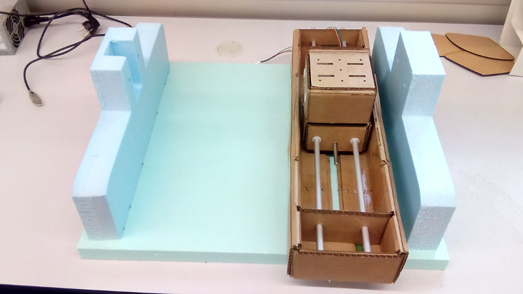
step 2: press-fit the second stage on top of the roofmate battlements. The stage sould fit perfectly. Pay attention to the side of the motor. As mentioned before, the pocket on the roofmate is ment to wrap the motor.
step 3: slightly elevate the lower stage and align it with the holes on the roofmate. Then run through the aluminium rails until it reaches the other side.
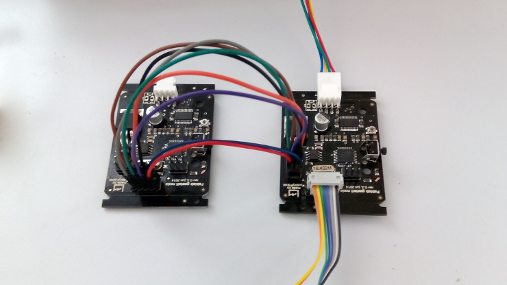
Hooking the two nodes
It's as easy as following the image below.
The problem for us was that we had no more 4x2 quickies to use here, instead we used male jumper wires transformed in female to successfully connect the two nodes.
xy_plotter.py test