
BADUINO BREAKOUT`
This week was broken up as we all attended the Wellington Open source conference. It was an amazing 2 day event that covered everything open source. I learnt much about how the result this project might work, with community or even as a business. However, it took 2 days away from the time I would spend doing fab academy work.
Because of this I have decided to do Charlieplexing, as it is new, but easy enough for me to get the hang of pretty quickly.
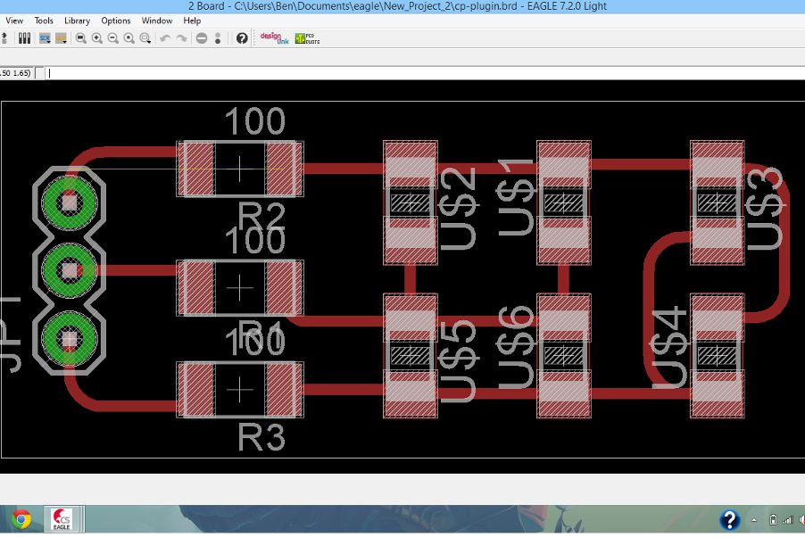
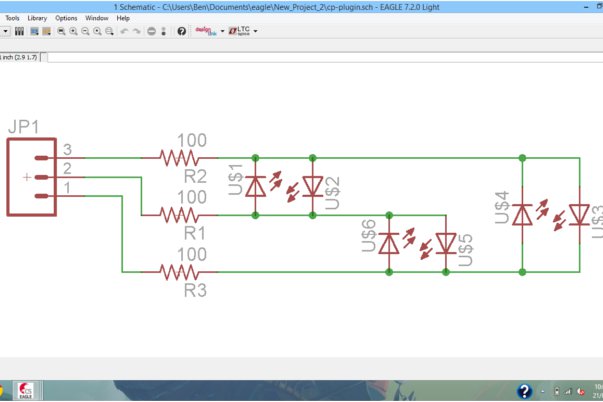
Charlieplexing is the technique of using microcontroller pins to make LED’s light up in an array. Because you can use pins as either the source or receiver of the signal you can light up more LED’s than you have pins, and because LEDs are diodes the LED receiving the reverse signal wont light up. If you want to learn more about charlieplexing you can look here for an easy instructable tutorial, or here for a more in depth article, both of which are extremely useful.
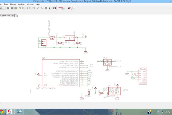
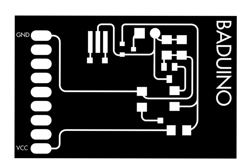
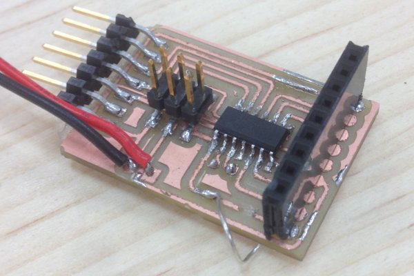
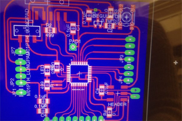
While I was designing the schematic file I realised I was using the same 5 components for every board I made, a screw terminal for the battery, a p channel mosfet for polarity protection, a voltage regulator with decoupling capacitors, an avr isp header and a ftdi header for the Attiny44. So I decided to make a board with just these components and pins to plug everything else in. I thought it would work kind of like a bad arduino, or a Baduino (on account of using an Attiny instead of the bigger and more powerful Atmega).
Designing the board was easy, but when it came time to sorting out the rats nest I decided I wanted to make a double sided board as as new experience and to separate components so that the board was easier to read. I also designed the charlieplexing plug in board along side it (although this one was much simpler to design).
There were multiple issues when it came time to cut the Baduino. Firstly we (fellow fab academy student Geoff and I) exported the eagle file incorrectly, and after cutting the holes and vias wrong, needed to invert the png colours.
Then when it came time to cut the other side. Everything was working fine to begin with. we used the same area to cut the other board and made the bads big enough so that if the vias and holes were unaligned it wouldnt matter too much. I then cleaned up the furry traces with an old broken 1/64 bit which worked a treat.
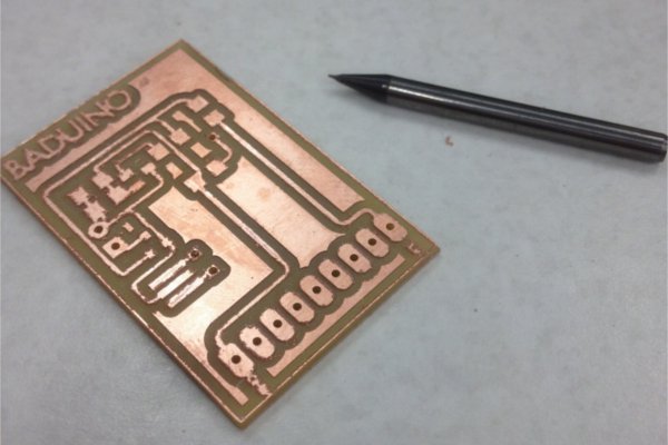
The problem arose when we didn't realise that we needed to mirror the image so that the top and bottom would line up. But when it came time to solder, we realised that flipping the board meant that it was impossible to solder up the position specific components (the Attiny and p channel mosfet) without soldering them upside down. As of yet I haven't found a solution to this issue but I would like to develop this board further as I imagine it will save me a lot of time and effort in the future. I invite anyone to download the files in the downloads page to see if they can get it working.
In the meantime I decided to try and test my charlieplexing board with an arduino uno. It worked to varying success, with LED’s lighting up, but not all of them or in the right order. I used the (link: http://playground.arduino.cc/code/charlieplex) charlieplexing library in the Arduino IDE which made the whole process simple. I will look into fixing this in the future also.
Overall this was a really fun, although exhausting week. I look forward to next week, which will be really important to my final project.
MILLING AND TROUBLESHOOTING
After regional review, I decided to ask around for ideas to solve my breakout board problem. It seems that what I missed was that in eagle when using the mirror tool, the poles of the components are flipped automatically. The reason I didnt notice is because you can only look at both top and bottom traces from the top view (as far as I can tell). Simply flipping the image vertically (and flipping the board the same way) solved that issue.
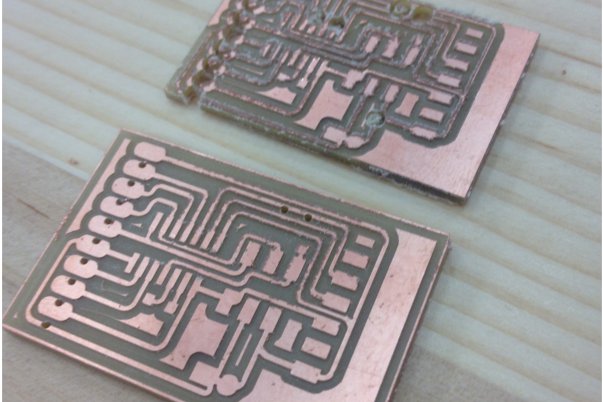
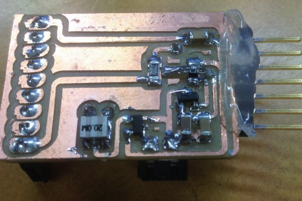
The next issue was that when milling the board, the double sided tape was not sticking well to one side, while milling the other. This resulted in some very questionable trace paths, which I had to solve with a blade and some wires. The result was a very sloppily soldered board (not my best work).
I have just tried attaching a battery to it, and poking it with a multimeter to test the voltage supplied to various parts of the board.The Attiny returned a voltage of 2 volts. Confused, I asked fab academy collegue and life-wizard Bry to help. He hacked away at it and diagnosed the problem. It seems relying on using the 0.1 pin headers to carry voltage from the top to the bottom of my board was a bad idea, especially as I didnt solder both sides of the board before sticking the pins in. The pin header was creating a resistance which dropped the voltage significantly.
However when it came time to burn the bootloader (with the Arduino IDE) it returned this error:
avrdude: initialization failed, rc=-1 Double check connections and try again, or use -F to override this check.
as this is a hardware error (probably due to my horrible soldering) I thought it would be a good idea to just re-mill my board and give it another try tomorrow. This experience has taught me alot about milling double sided boards. Specifically:
- It is important that the decoupling capacitor sits as close to the Attiny as possible.
- Dont assume the pins connecting top and bottom traces will do so without resistance and make double sure to solder both sides.
- It might be a good idea to figure out a different way to hold the board down on the mdx-20 so that it wont come unstuck, maybe with a laser cut slot?
- Give your traces plenty of space and dont solder at the very end of the day. It usually goes badly.
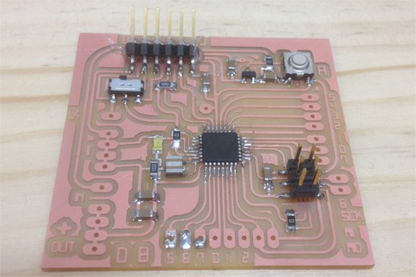
BABEDUINO
After about the fourth iteration of the Baduino, I thought it best to cut my losses and try and make a fabduino. Fortunately for me, Anna and Jasmin also both needed fabduinos for their final projects. I jumped at this opportunity to work in a group to get it done.
My contribution was mainly dealing with the rats nest (a job that nobody else wanted), but I did help with one specific aspect of the board. This was power managment.
Basically, we wanted to have the option to power the board with a battery or external source, which then made a voltage regulator nessecary. The mistake we made to begin with was to confuse voltage in and voltage out (to power other boards broken out).
We solved this with a simple switch and 4 power lines:
- VCC unfiltered (a pad that assumes you will power the board with exactly 5 volts, or through the FTDI headers)
- VCC filtered (a pad that assumes the power will be unfiltered and runs through the voltage regulator)
- VCC out (which you would power any external boards with)
- GND, which is ground.
After this it was just a case of milling and soldering, which because we made the Atmega pads really long, was no problem at all!
You can read about the Babeduino in more depth on Jasmins blog.
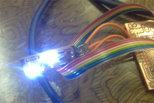
CHARLIEPLEXING SUCCESS
Once I had finished the babeduino, it was a simple matter to finish the charlieplexing breakout board I had made previously.
There were only two problems, both easy fixes. The first was that the third pin of the breakout board wasnt working, which made half the LEDS not work. After consulting Craig who graciously helped me solve the problem, replacing the resistor for that pin solved the problem.
The second problem was that when I set up my code using the charlieplexing library, it would turn two LEDS on at the same time. I think this is because I could turn two pins high and low, but I couldnt put the third into high impedence mode. I decided to write my own code.
After a bit of research and this fantastic tutorial, I found out you could switch a pin to high impedence mode in arduino by setting the pin mode to "INPUT" and writing it "LOW".
From there I wrote a clear function to put all the pins into High impedence mode, and individual functions to turn each LED on. Easy.