FTDI SOLDERING HELL
I had an idea of what I wanted to do this week. I thought it would be easiest (and best) to try and get a rgb colour wheel to work with my RGB LED board. For this purpose I could find an already made program and try to understand how it worked. This was a good idea, as it is a pretty common project and I found a program for this in processing. Off to a good start.
While I was doing this I thought it would be a good Idea to develop an ftdi bridge that could work as a USB-Attiny bridge for serial communication. The plan was to work with Daniel to develop a bridge that would work with the Wellynet network we developed last week.
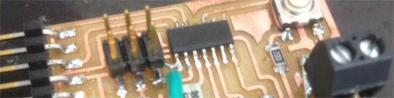
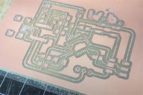
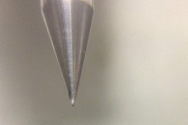
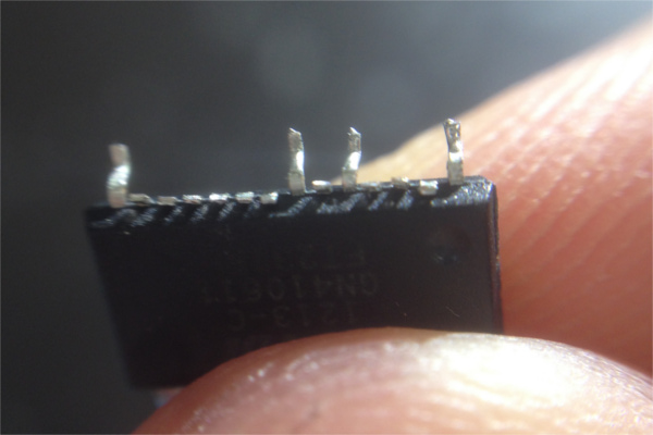
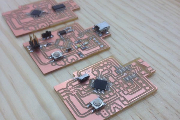
The design of the board was no problem, We decided to use an Atmega 368 (so that it could hold both software serial and wellynet libraries) as well as a Ftdi chip, crystal clock, two LEDs to show data on the Tx and Rx lines a LED for power, hardware reset button and switch to allow voltage on Wellynet and of course, Mini USB and AVRISP headers to connect to the computer. FTDI chips. To make the pads I had to use a 0.010 mm bit with a separate path. After reading Craigs blog it was easy to understand.
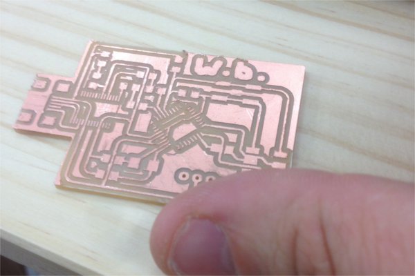
Soldering however, was a huge pain. Even with the smallest soldering tip, the legs for each chip were too small to not get solder on the other pins, and alignment was a huge problem especially for the Atmega, which had pins on all sides. I then tried to clip off all but the oins I was actually going to solder. Unfortunately this didnt work either as some of the pins I needed snapped off too. I tried for 2 days to get it right but after burning through 3 of each chips I decided to give up and figure out another solution later.
As for the actual programming, I looked into a few tutorials and due to Jasmin, found this simple, fantastic tutorial of processing. It will take a bit of time to learn but I will do my best.
Finishing interfaces
I decided that I wanted to get interfaces out of the way as fast of possible (it was one of the last things to do on my list, apart from finishing final project.) Because of this I decided to use processing, with the charlieplexing and babeduino boards I had made previously. I thought that I would want to use the RGB LED board I had done previously, however it uses a ATTiny which doesnt have serial support. I looked into using my babeduino as a serial converter with an FTDI cable, but this was going to take too long.
The first thing I did was finish watching the tutorials on processing and arduino, before looking for ways to get the two to talk. I came across this fantastic tutorial which was immensely helpful as a step by step guide to get both to talk.
I wrote a simple button code in processing and following the tutorial, modified my ardiuino code so that it would read serial data from processing. Both very easy to achieve.
Here is the Processing code:
import processing.serial.*;
//charlie plexing test 0.1 - Ben Matthes
int dragX;
int time;
int wait = 50;
Serial myPort;
void setup(){
size(400,400);
background(204);
time = millis();
String portName = Serial.list()[32];
myPort = new Serial (this, portName, 9600);
}
void draw(){
background(204);
fill(255);
if (mouseX < 50 && mouseY <50){
fill(0);
if(mousePressed == true && mouseButton == LEFT){
fill(126);
myPort.write('1');
println('1');
}
else{
myPort.write('0');
println('0');
}
}
rect(0,0,50,50);
}
And the modified charlie plexing arduino code:
static int LP1 = 5;
static int LP2 = 6;
static int LP3 = 7;
char val; //character read from serial
int dragDelay;


void LED_CLEAR(){
pinMode (LP1, INPUT);
pinMode (LP2, INPUT);
pinMode (LP3, INPUT);
digitalWrite (LP1, LOW);
digitalWrite (LP2, LOW);
digitalWrite (LP3, LOW);
}

void LED_WRITE1(){
  LED_CLEAR();
  pinMode (LP1, OUTPUT);
  pinMode (LP2, OUTPUT);
  pinMode (LP3, INPUT);
  digitalWrite (LP1, HIGH);
  digitalWrite (LP2, LOW);
  digitalWrite (LP3, LOW);
}
void LED_WRITE2(){
  LED_CLEAR();
  pinMode (LP1, OUTPUT);
  pinMode (LP2, OUTPUT);
  pinMode (LP3, INPUT);
  digitalWrite (LP1, LOW);
  digitalWrite (LP2, HIGH);
  digitalWrite (LP3, LOW);
}
void LED_WRITE3(){
  LED_CLEAR();
  pinMode (LP1, OUTPUT);
  pinMode (LP2, INPUT);
  pinMode (LP3, OUTPUT);
  digitalWrite (LP1, LOW);
  digitalWrite (LP2, LOW);
  digitalWrite (LP3, HIGH);
}
void LED_WRITE4(){
  LED_CLEAR();
  pinMode (LP1, INPUT);
  pinMode (LP2, OUTPUT);
  pinMode (LP3, OUTPUT);
  digitalWrite (LP1, LOW);
  digitalWrite (LP2, HIGH);
  digitalWrite (LP3, LOW);
}
void LED_WRITE5(){
  LED_CLEAR();
  pinMode (LP1, INPUT);
  pinMode (LP2, OUTPUT);
  pinMode (LP3, OUTPUT);
  digitalWrite (LP1, LOW);
  digitalWrite (LP2, LOW);
  digitalWrite (LP3, HIGH);
}
void LED_WRITE6(){
  LED_CLEAR();
  pinMode (LP1, OUTPUT);
  pinMode (LP2, INPUT);
  pinMode (LP3, OUTPUT);
  digitalWrite (LP1, HIGH);
  digitalWrite (LP2, LOW);
  digitalWrite (LP3, LOW);
}

void setup() {
  Serial.begin(9600);
}

void loop() {
  if (Serial.available()){
    val=Serial.read();
  }
 if (val == '1'){
   LED_WRITE1();
   delay(50);
   LED_WRITE2();
   delay(50);
   LED_WRITE3();
   delay(50);
   LED_WRITE4();
   delay(50);
   LED_WRITE5();
   delay(50);
   LED_WRITE6();
   delay(50);
   LED_CLEAR();
   delay(50);

 }
 else{
   LED_CLEAR();
   delay(10);
 }
}
I was having problems getting my babeduino talking to my computer, and then remebered Jasmin had this same problem, and solved it here. Basically we had our RX and TX pins swapped over. An easy fix.
I think processing is a very easy program to use, however I am not really used to graphics based coding, so it took a while to get used to after working primarily in the Arduino IDE. I will need to practise some more if I am going to continue this type of coding. Like wise, looking into serial communication a bit more seems like it could be a good idea.