DEALING WITH RESISTANCE
This week started with a very very hard video lecture, especially when I was only just recovering from a nasty cold. The lecture was full of complicated relationships between components, to the point where I only barely understood the assignment. I have always had a love hate relationship with electronics design (which I was reminded of in the Electronics production assignment), and this week I was reminded why.
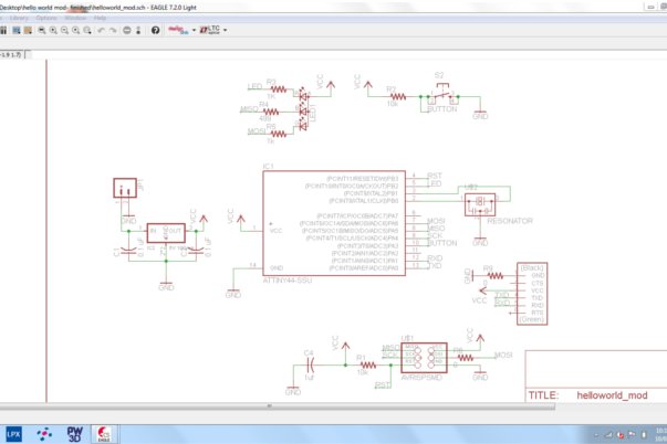
The first day was spent with collegue (and electronics wizard) Craig, teaching us all about the workflow of Eagle (the schematic board software we decided to use as a group) and the brader workflow of electronics design. I think we all owe much to Craig this week for basically holding our hands through the assigment. At the end of the day our brains were all mildly fried, so we decided to call it a day and begin the true work of eagle tomorrow.
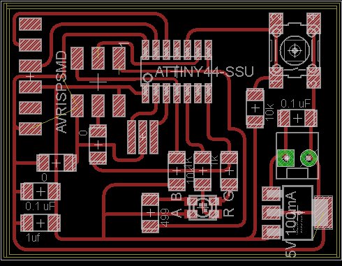
Day two was spent actually making the board, the schematic of which was simple enough. Most of it was just loading the right libraries in and using the right parts. This part of the assigment was made especially easy with the fab academy tutorial expertly written by Anna. However, when moving on to adding our own parts the assignment became much more difficult. I decided to add a voltage regulator with capacitors on each side (what I would later be alterted were called decoupling capacitors). I needed to find out the capactiance of said capacitors, which was achieved by looking up the data sheet (after being pointed there by my electrical engineer cousin).
The second problem was adding a RGB LED (the only one on the fab academy inventory and eagle library). I first was told that there are two types of RGB LED's, Anode or Cathode common. These dictate the direction of the logic board, LED circuit. Because the LED was Cathode common, it meant that the power was going to sunk (or ended) at the logic board. There were two problems, first each LED colour had it own peak current which needed its own resistor. Second, the tiny44 has maximum input current of 40 mA, which was fine for the Green and Blue LEDs (which had a peak current of 20 mA) but not for the RED LED (which had a peak current of 50 mA).
We needed a way to determine what resistors to use. V=IR was the equation used to etermine the resistors, but the question was: is the votage part of the equation the input voltage (5V) the forward voltage of the RGB LED, or the subtraction of one from the other? The answer would determine if it were possible to use an RGB LED, as we only have select resistors in the Wellington Fab Lab.
On monday, I was shown the answer to my RGB problem. The trick was finding out the right sized resistors, then using the next closest resistor. Sure LED would be a little dimmer, but at least it worked. Hving a look at the output devices showed me that using two 1000 ohm and a 499 ohm resistor should work fine.
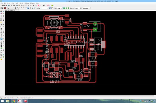
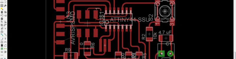
from there it was simple to finish the schematic by linking up and labelling all the appropriate parts. Unfortunately I was not prepared for what came next: the rat's nest. Sorting out the rat's nest reminded me of a game called flow. It is easy in that you can see how all the peices fit together, although making it all work takes an extrodinary amount of time and effort.
Having put all that effort in, I now approach it like a puzzle, and have three simple tips for anyone else attempting to do this for the first time:
- The hardest part to deal with is usually the links between logic board and compnents without a gap underneath (for the sake of these tips we will call components like resistors or capacitors with space between eagle pads, jumpers). Deal with the components that need direct uninterrupted link between attiny and/or ISP pins first.
- the next thing to deal with is the links between components and other components without needing a link to vcc, ground or logic board or ISP pins. You can use these component chains to jump over pre-exsisting links.
- the final thing to worry about is the vcc and ground links. Most of your components will need a link to either vcc or ground. It is common to have long paths of vcc and ground running through the entire board attaching to many different components.
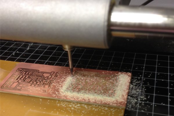
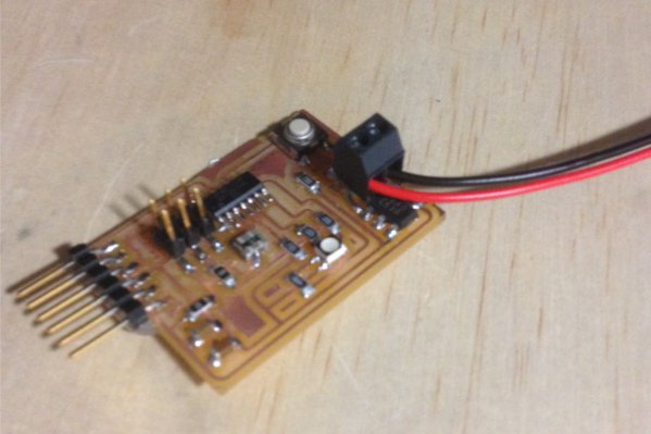
Having spent nearly two days figuring out the rat's nest, I finally had something printable. Milling out the board and stuffing it was surprisingly easy after all the practise I had last week. I am quite proud of the first board I actually designed, and allthough simple, I am veryexcited to spend some time programming it next week!