
14. Interface and Application programming
write an application that interfaces with an input &/or output device
This week’s my goal is having experience with different interface and application programming languages.
Processing
- Interfacing with my Input device (z-axis accelerometer)
I used processing to visualize the data stream. I have some experience with Processing language. It is a useful software for visualisations and graphic experiments.
Arduino Code
I change the arduino code on the input device to send the sensor’s data to serial port. I tested with FTDI and serial monitor. When I hold the sensor vertically, the minimum value was about 450. And when I hold it horizontally, the maximum value was about 680. so I change the value to
SoftwareSerial serial(0, 1); //TX, RX at ATtiny 44, 20MHz external void setup() { serial.begin(9600); pinMode(7, OUTPUT); //led on the board digitalWrite(7, HIGH); //turn on the led } void loop() { long val; val = analogRead(3); //save the sensor value to val val = map(val, 450, 680, 0, 1023); val = constrain(val, 0, 1023); serial.println(val); //send the data to serial delay(10); } |
Processing Code
I wrote a very simple code that expresses receiving data to circle’s dimension. when I hold the sensor vertically, the circle’s diameter is zero.
int i; Serial myPort; float data; public static int ON = 1; public static int OFF = 0; void setup() { size (1200, 800); // set resolution delay(3000); // make delay for communication well String portName = Serial.list()[2]; //select serial port in the Serial list println(Serial.list()); myPort = new Serial(this, portName, 9600); } void draw() { background(255); //background color - write ellipse(600,400,data,data); //make circle, the center is (600,400), fill(0,0,0); //the color inside of the circle is black. } void serialEvent(Serial p) { String message = myPort.readStringUntil(10); // if (message != null) //when there is a data, { print("Received: "); //print the data println(message); data = float(message); //save the data } } |
Add #1 OpenCV with Raspberry pi and pi camera module
For final project, I made a application using openCV with Raspberry pi and pi camera module
Raspberry pi setup
It was almost my first raspberry pi project. so I struggled even when I start linux. I have a Raspberry pi Model B. And I followed this tutorial.
1.
downloaded OS image file (raspbian) from the page
2. put SDcard in raspberry slot, connect mouse, keyboard, HDMI Cable, micro USB cable.
3. the Power LED is turned on but the lcd didn't get any signal
4. I solved this in config.txt (link). opened the file and changed to hdmi_force_hotplug=1 . then It worked.
Display(LCD) setup
I have a 7'' tft lcd module (CLAA070NC0BCT : datasheet). It is interfacing with LVDS, so I needed to HDMI to LVDS converter like this. but I decided to use DVI to LVDS converter since I could easliy get from a local shop. It was around 30 US dollars. Then, I also needs HDMI to DVI cable.
Pi camera setup
Why Pi-camera module?
I chose The Pi camera module rather than USB webcam. I found the reason at this forum "it's 'run' by the GPU and can dump full frames into RAM at 15 frames a second this is 7.5MB/frame, 15fps = 112.5 Mega BYTES per second .. or you can have full HD resolution 30fps H264 encoded (by the GPU) along with some simultaneous still photos (Google MMAL) all at virtually zero CPU loading"
Get started
Very well documentation on this page
1. The flex cable inserts into the connector situated between the Ethernet and HDMI ports
2. Boot up the Pi and log in
3. sudo apt-get update (It must be online, I failed at first time because I didn't check the wifi connection)
4. sudo apt-get upgrade
5. sudo raspi-config, Navigate to “camera” and select “enable”.
6. Select “Finish” and reboot.
Using MMAL library and raspivid/raspistill source code
I tried to follow this tutorial. However, I failed on step:3 when I compiled it. It seems that everyone get hard times at same reason. I struggled with it and spent a lot of time because of my lack of knowledge about linux and e. I decided to look for another mothod.
I solved with v4 l2 driver. I followed the instruction on this page (korean)
1. enable the camera
pi@rasplay ~ $ sudo raspi-config
2. Activate the v4l2 driver
pi@openmake ~ $ sudo modprobe bcm2835-v4l2

pi@openmake ~ $ ls /dev/video0
/dev/video0
3. Get registration key
pi@rasplay ~ $ wget http://www.linux-projects.org/listing/uv4l_repo/lrkey.asc && sudo apt-key add ./lrkey.asc
4. Install the package
pi@rasplay ~ $ sudo apt-get install uv4l uv4l-raspicam
5. test
pi@rasplay ~ $ uv4l --driver raspicam --auto-video_nr --width 640 --height 480 --encoding jpeg --frame-time 0


openCV_split.cpp
#include “opencv2/highgui/highgui.hpp”
       #include <iostream>
using namespace std;
       using namespace cv;
int main(int argc, char** argv){
       VideoCapture cap(-1);
       if (!cap.isOpened())
       {
       cout << “Cannot open camera” << endl;
       return -1;
       }
       cap.set(CV_CAP_PROP_FRAME_WIDTH, 640);
       cap.set(CV_CAP_PROP_FRAME_HEIGHT, 480);
namedWindow(“Output1”,CV_WINDOW_AUTOSIZE);
namedWindow(“Output2”,CV_WINDOW_AUTOSIZE);
while (1)
       {
       Mat frame;
       bool bSuccess = cap.read(frame);
if (!bSuccess)
       {
       cout << “Cannot read a frame from camera” << endl;
       break;
       }
       imshow(“Output”, frame);
if (waitKey(30) == 27)
       {
       cout << “Exit” << endl;
       break;
       }
       }
       return 0;
       }
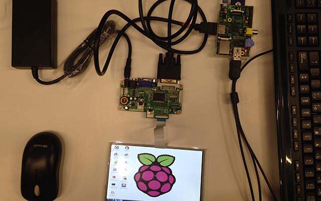
Preparations : 1080X760 LCD module, 12V 5A power supply, HDMI to VGA connector,
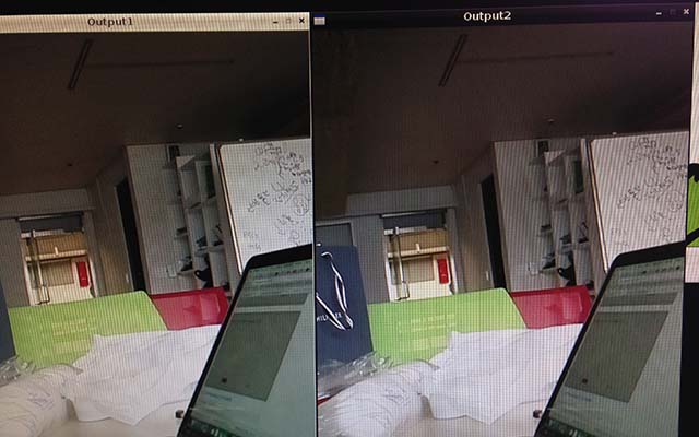
output are two seperate windows from one pi camera module