
11. Output Devices
Add an output device to a microcontroller board you've designed and program it to do something
Light Interactive Window Blind
Stepper motor + Light sensor
Stepper driver download files (eagle, png, rml..)
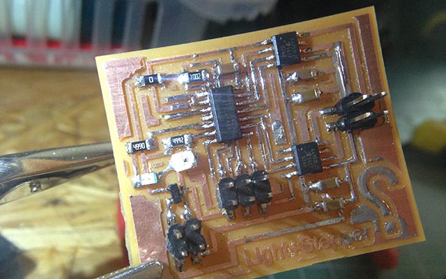
I’m going to make automatic window blind which interact with lights. I’m going to stepper motor to roll the window blind. I design the board which has a microcontroller ATtiny44, H bridges, photo-transistor
 |

|
 |
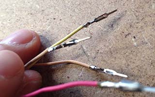
Which one have 4wires are Bipolar steppers. |
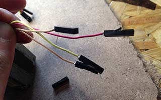
Female connectors |
soldering, wire connections |
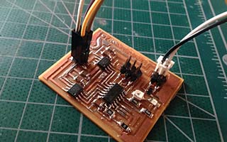
Serial Communication wire connections |

if Light sensor Value is higher than a threshold, it rotates 2000 steps (depends on blinds) clockwise
Also if Light sensor Value is lower than a threshold,it rotates 2000 steps (depends on blinds) counter-clockwise
#include <SoftwareSerial.h>
     SoftwareSerial serial(0, 1);
int motorPin1 = 0;
       int motorPin2 = 1;
       int motorPin3 = 3;
       int motorPin4 = 4;
       int sensorPin = 7;
       int delayTime = 1000;
       int sensorValue = 0;
       int distance = 0;
void setup()
       {
       serial.begin(9600);
       pinMode(motorPin1, OUTPUT);
       pinMode(motorPin2, OUTPUT);
       pinMode(motorPin3, OUTPUT);
       pinMode(motorPin4, OUTPUT);
       }
void loop()
       {
       sensorValue = analogRead(sensorPin);
       if(sensorValue<500){
       if(distance<3000){
       digitalWrite(motorPin1, LOW);
       digitalWrite(motorPin2, HIGH);
       digitalWrite(motorPin3, HIGH);
       digitalWrite(motorPin4, LOW);
       delayMicroseconds(delayTime);
       digitalWrite(motorPin1, LOW);
       digitalWrite(motorPin2, HIGH);
       digitalWrite(motorPin3, LOW);
       digitalWrite(motorPin4, HIGH);
       delayMicroseconds(delayTime);
       digitalWrite(motorPin1, HIGH);
       digitalWrite(motorPin2, LOW);
       digitalWrite(motorPin3, LOW);
       digitalWrite(motorPin4, HIGH);
       delayMicroseconds(delayTime);
       digitalWrite(motorPin1, HIGH);
       digitalWrite(motorPin2, LOW);
       digitalWrite(motorPin3, HIGH);
       digitalWrite(motorPin4, LOW);
       delayMicroseconds(delayTime);
       distance++;
       }
       else{
       digitalWrite(motorPin1, LOW);
       digitalWrite(motorPin2, LOW);
       digitalWrite(motorPin3, LOW);
       digitalWrite(motorPin4, LOW);
       }

       }
       if(sensorValue>=500){
       if(distance>0){
       digitalWrite(motorPin1, HIGH);
       digitalWrite(motorPin2, LOW);
       digitalWrite(motorPin3, LOW);
       digitalWrite(motorPin4, HIGH);
       delayMicroseconds(delayTime);
       digitalWrite(motorPin1, LOW);
       digitalWrite(motorPin2, HIGH);
       digitalWrite(motorPin3, LOW);
       digitalWrite(motorPin4, HIGH);
       delayMicroseconds(delayTime);
       digitalWrite(motorPin1, LOW);
       digitalWrite(motorPin2, HIGH);
       digitalWrite(motorPin3, HIGH);
       digitalWrite(motorPin4, LOW);
       delayMicroseconds(delayTime);
       digitalWrite(motorPin1, HIGH);
       digitalWrite(motorPin2, LOW);
       digitalWrite(motorPin3, HIGH);
       digitalWrite(motorPin4, LOW);
       delayMicroseconds(delayTime);
       distance--;
       }
       digitalWrite(motorPin1, LOW);
       digitalWrite(motorPin2, LOW);
       digitalWrite(motorPin3, LOW);
       digitalWrite(motorPin4, LOW);
       }
       }
Hello RGB
Hello RGB download files
I downloaded the design files and milled the board from fab academy archive. I used both arduino and C to program it.
What is a RGB LED?
I looked at the Datasheet of the RGB LED. It is a set of 3 LEDs (red, green, and blue). so the interest thing is that the property of the component are different with colors. here is the summary I made.
this is a very small component (3.2mm X 2.8mm) for full color video screens or lightings. Maximum Forward currents are 50mA for red, 25mA for green and blue. Avarage Forward voltages are 2.0V(red), 3.2V(green) at 20mA. If it goes same current in every colors, than green is the bright one. It is a RoHS Compliance components that means restriction of the use of certain hazardous substances.
Arduino
tools -> Clock -> 8Hz(internal)
tools -> Processor -> ATtiny45
red=2(PB2) green=0(PB0) blue=1(PB1)
using analogWrite function to make PWM control
Arduino Code - Change 6 colors mode
C code
Hello Servo
Hello Servo download files
I downloaded the design files and milled the board from fab academy archive. I used both arduino and C to program it.
What is a servo motor?
I read the brief datasheet of the mini servo motor(SG90). It was very helpful to understand how it works and program it. here is the summary.
It can turn 180 degree between -90 to 90. Weight : 9g, stall torque : 1.8kgf*cm (torque produced by a mechanical device whose output rotational speed is zero) Operating speed : 0.1s/60 degree, Operating Voltage : 4.8V, Dead band width: 10 µs (how accurate the servo try to hold the exact center position) Position "0" (1.5 ms pulse) is middle, "90" (~2 ms pulse) is all the way to the right, " " -90" (~1 ms pulse) is all the way to the left.
C - I tried to modify the code to make servo move smoothly.
download C files