
10. Input Devices
measure something: add a sensor to a microcontroller board that you've designed and read it
I have to measure head motion for My final Project. 3-axis accelerometer and gyroscope sensor is needed for that. In this week I tried to add accelerometer to a micro controller board.
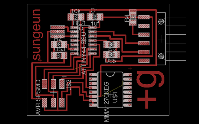
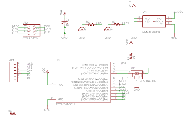
First, I tried with MMA8452qt and but failed because the traces are too thin. Second, I made a board with Z-axis accelerometer MMA1270KEG.
Z-Axis accelerometer
datasheet : MMA1270KEG
I got a reference from www.diy-devices.com
 |
 |
Programming
I programmed with Arduino IDE. It gathers sensor's value twenty times for making the maximum value and the minimum value. If the difference with the maximum and minimum value is bigger than 100, LED output is changed.
SoftwareSerial serial(0, 1); { serial.begin(9600); pinMode(7, OUTPUT); digitalWrite(7, HIGH); } { long val, minval = 1023, maxval = 0; for (int i = 0; i < 20; i++) { val = analogRead(3); if (val > maxval) maxval = val; if (val < minval) minval = val; } //analogWrite(0, 255 - constrain(map(maxval - minval, 100, 1023, 0, 255), 0, 255)); if (maxval - minval > 100) { if (lightOn == true) { digitalWrite(7, LOW); lightOn = false; } else { digitalWrite(7, HIGH); lightOn = true; } delay(1000); // wait a second so as not to immediately toggle the light again } serial.print(minval); serial.print("\t"); serial.print(maxval); serial.print("\t"); serial.println(); } |
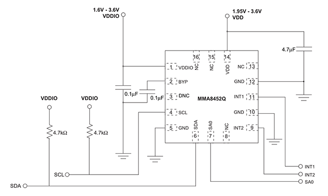
3-Axis accelerometer
datasheet : MMA8452qt
download files
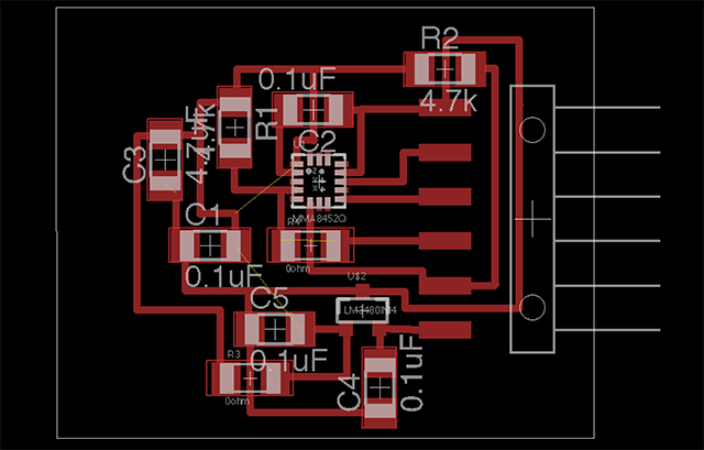
There is MMA8452qt in our inventory. I looked at the datasheet for make PCB design. I made sensor shield using I2C communication with fabduino. I also made fabduino from fabkit vr.2.
-
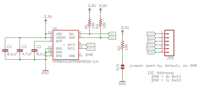
download the eagle library file from Sparkfun
-
draw Schematics and routed it. I figured out pin configuration in datasheet and I got a reference from SparkFun Triple Axis Accelerometer Breakout. the pictures below are the Pin configurations and eagle files. I added regulator for change voltage from 5V to 3.3V. and one jumper resistor.
 |
 |
 |
-
Export PNG file, and make the trace and outline image files using GIMP. same as week 5 electronic design.
-
Make toolpath files (rml files) for the SRM-20 in Fabmodule. There is a trick to make a path thinner than the tool diameter (0.4mm), I set tool diameter as 0.35mm. If I said 0.4mm to fabmodule, It cannot route the line where sensor will be attached.
cutting parameters : speed(4mm/s), cut depth(0.1mm), number of offsets(-1), offset overlap(50%),
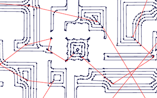 tool diameter - 0.4mm |
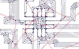 tool diameter - 0.35mm |
Failures
the traces are too thin so easily broken like the picture below. I tried soldering with this using heat gun. but failed as you can see the picture on the right. maybe I could get it with thinner mill or another shape one. also I can try with a pick&place machine.
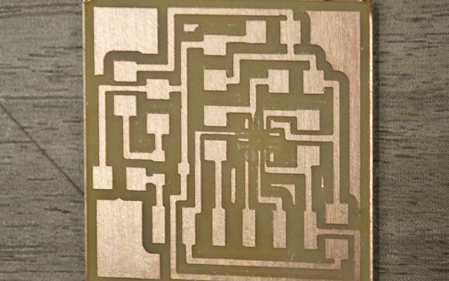 |