
7. Embedded Programming
Read a microcontroller data sheet, program the board
I have experiences with arduino IDE, but It was first time with my own board and ISP. I’m reading a ATtiny’s datasheet.
Download files (firmware, Sketches)
Summary a microcontroller data sheet
ATtiny24/44/84 is a low-power CMOS 8-bit microcontroller based on the AVR enhanced RISC architecture.
Pin descriptions
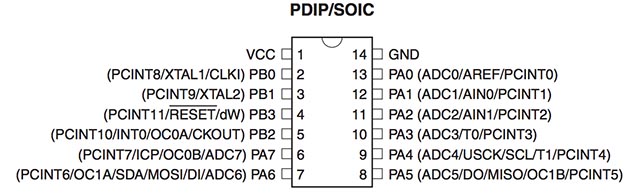
VCC : Supply voltages
GND : Ground
Port B (PB3:PB0) : 4-bit bi-directional I/O port with internal pull-up resistors.
RESET(PB3) : Reset input. A low level on this pin for longer than the minimum pulse length will generate a reset.
Port A (PA7:PA0) : Port A is a 8-bit bi-directional I/O port with internal pull-up resistors. Port A has alternate functions as analog inputs for the ADC, analog comparator, timer/counter, SPI and pin change interrupt.
Googling the terms
-
RISC (Reduced Instruction Set Computer) : Attiny has advanced RISC Architecture. It is a CPU design strategy based on the insight that a simplified instruction set. The opposing architecture is called complex instruction set computing
-
EEPROM (128/256/512 Bytes of In-System Programmable EEPROM) : Electrically Erasable Programmable Read-Only Memory, Non-volatile memory. used in computers and other electronic devices to store small amounts of data that must be saved when power is removed
-
PDIP/SOIC : PDIP(Dual in-line package, through hole package), SOIC(Small-outLine integrated circuit)
peripheral : device that is used to put information into or get information out of the computer. there are two different types of peripherals: input devices and output devices.
CPU Core
1. ALU - arithmetic Logic Unit : arithmetic logic unit (ALU) is a digital electronic circuit that performs arithmetic and bitwise logical operations on integer binary numbers. It is a fundamental building block of the central processing unit (CPU) found in many computers.
2. Status Register : The Status Register contains information about the result of the most recently executed arithmetic instruction
3.General Purpose Register File : Most of the instructions operating on the Register File have direct access to all registers, and most of them are single cycle instructions. each register is also assigned a Data memory address, mapping them directly into the first 32 locations of the user Data Space.
4. Stack pointer : The Stack is mainly used for storing temporary data, for storing local variables and for storing return addresses after interrupts and subroutine calls.
5. Instruction Execution Timing : The AVR CPU is driven by the CPU clock clkCPU, directly generated from the selected clock source for the chip. In a single clock cycle an ALU operation using two register operands is executed, and the result is stored back to the destination register.
Arduino IDE
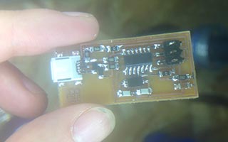
I used arduino IDE to program Attiny44. but I failed several times. It was because of the FabISP board what I made in 4th Assignment. I made a new FabISP, and I succeed. I guess the reason is the smoke there was a little when I programmed the FabISP with wrong connection. I followed this instruction. this tutorial said how to program Attiny microcontrollers with Arduino IDE.
 |
 |
-
Download Arduino IDE 1.6.x (OSX version)
-
Install ATtiny support
unzip the attiny zip file -> locate in Arduino sketchbook folder. -> create folder called hardware -> copy “attiny” folder from Attiny unzip file -> restart Arduino IDE -
Tools -> Board -> Attiny
Tools -> Clock -> 20MHz clock
Tools -> Processor -> Attiny44
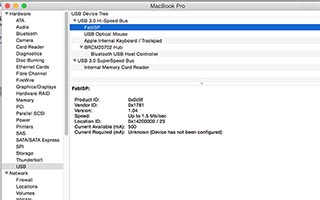
Tools -> Programmer -> USBtinyISP -
Powering the hello-echo board. Connecting hello-echo board with FTDI Basic board. (Mac OSX FTDI driver) It looks like the picture below
-
Burn bootloader
-
Upload Sketch
Arduino Sketch
-
int led = 7; //led is on pin7, I could find it on datasheet (PA7)
void setup() {
pinMode(led,OUTPUT); //pin7 is to make digital output pin.
}
void loop() {
digitalWrite(led,HIGH); //make pin7 to +5V, turn on the led
delay(1000);
digitalWrite(led,LOW); //make pin7 to GND, turn off the led
delay(1000);
}
- using button
int led = 7;
int button = A3; //button is connected with PA3(ADC3/T0/PCINT3) on datasheet
void setup() {
pinMode(led,OUTPUT);
}
void loop() {
if(digitalRead(button)==HIGH){ //if button pressed, PA3 pin is LOW(+5V)
digitalWrite(led,HIGH);
}
else{
digitalWrite(led,LOW);
}
}