HOME
1. Vimeo Links : One, Two
2. Assignments : Measure something: add a sensor to a microcontroller board that you've designed and read it
3. Tryouts
A. For this week, I made the magnetic sensor input.
So the steps are:
1) Make an magnetic input sensor board
2) Program ISP
3) Download PySerial
4) Compile python
B. I downloaded the traces and interior files from the link.
http://academy.cba.mit.edu/classes/input_devices/index.html
And I used the fabmodules.org to have PCB milling RML files.
I made the board from the Rolans SRM-20 just like WEEK 4.
I soldered the necessary component and it was done.

C. Now Hardware is done. From here, move on to the Software.
1) Prepare Fab ISP Board from WEEK 4.
2) Since I am going to check the input sensor by the serial, Install Python Serial.
http://pyserial.sourceforge.net/
3) Download the following files to the terminal directory(for me, Machintoshi HD/Users/kdoodoo/).
- Files are c, make, python: hello.temp.45.c makefile hello.temp.45.py
- Download from : http://academy.cba.mit.edu/classes/input_devices/index.html
4) Connect Fab ISP with the input board.
5) Run Terminal to program the input board.
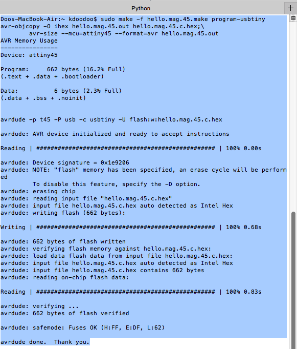
Type: sudo make -f hello.mag.45.make program-usbtiny

If the board is programmed it would look like this.

6) After programming, now we need to find where the serial port is.
Type: ls /dev/tty.*

Then the result is:

Copy the location. /dev/tty.usbserial-A5025URR
7) Insert the copied location to the python code and type at the terminal.
python hello.mag.45.py /dev/tty.usbserial-A5025URR

8) Then, it works well.
(Make sure the FTDI connection to the input board. I plugged in the other way and took me a while to figure things out.)
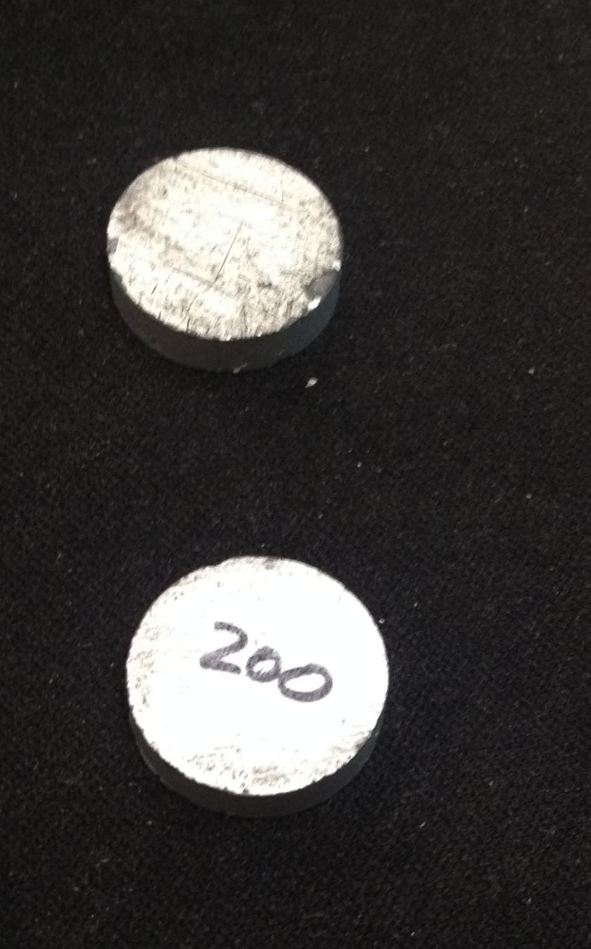
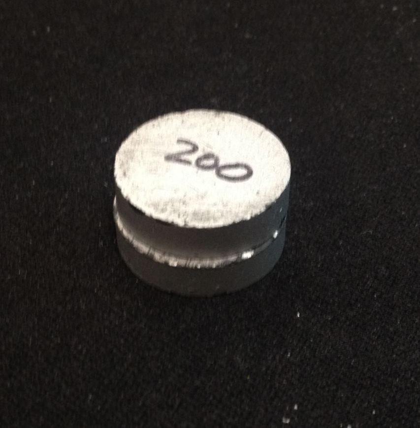
9) I tested with these magnets.


D. Here are the videos.
1) Tested with ONE MAGNET
2) Tested with TWO MAGNETs
I changed the COLOR of the python.