Electronics design
Software (Eagle CAD)
Tutorial Link :
http://fabacademy.org/archives/2015/doc/electronics_design_eagle.html
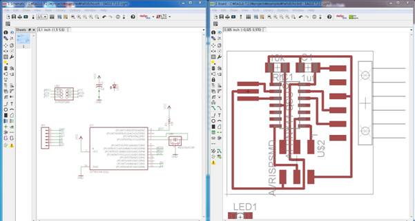
Left is Schematic, the other side is Board. Add components and put on Schematic and name the components be a circuit.
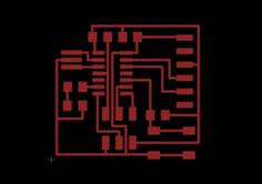
Converse screen to the “Board” all the traces are connect and now I can modify not to cause any interferences.
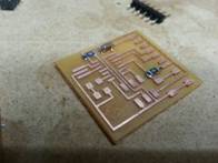
Redesign the board
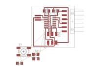
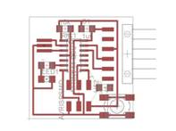
To rearrange switch and LED, load original Hello Board, add up Switch and LED on Schematic. To make it compact I put effort to well arrange the board.
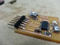
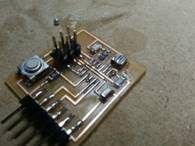
Soldered by resistance, ATTint, pin sequence.
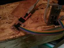
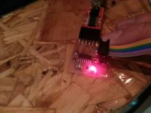
Upload with FTDI and FabISP and push the switch, voila! LED turned on.
Problem and Solving
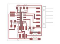
When I exportthe file with original setting on Eagle CAD it comes out with black background. And export just a “trace” with PNG file, Trace was a black the other area was white.
To solve this problem I simply can use GIMP or Photoshop to reverse its’ color but I want to solve it by Eagle CAD. So I googled it.
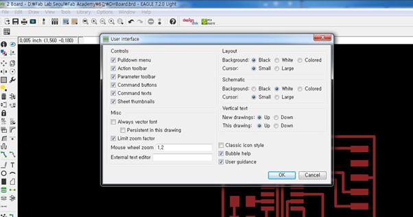
Enter the “User interface” menu and “Background” in “Layout” tab was selected as a “black” so, change it with “white” than you can get what you expected.
TIPS
- Usually resistances tolerance is 1% ~ 5% and it never bothers us in this step.
- Difference between Crystal and Resonator is Crystal has capacitor on each side but Resonator doesn’t have.
- In diode electric currency flow from Anode to Cathode.
- In case of chip LED there is no line distinguish which is Anode or Cathode, You should test yourself and solder it to gather.
Download files
Redesign board