Computer-aided design
2D Design Illustrator
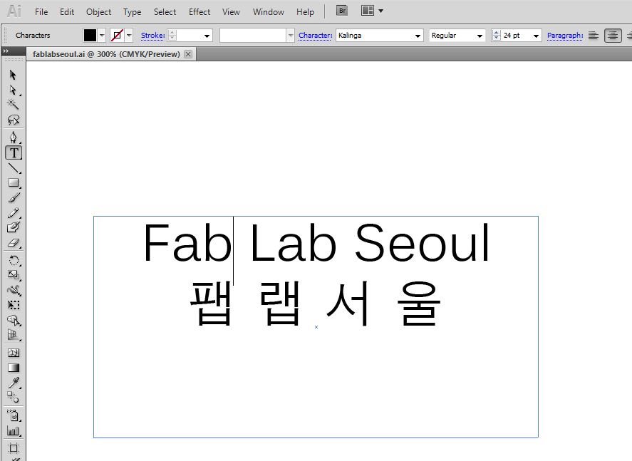
Using 2D Design tool(illustrator), I designed Fab Lab Seoul Font. I tried to changing various fonts, font size, font style and align.
2D Design also can be designed in 3D CAD Modeling tool. So, When i draw 3D Modeling in UG-NX(3D CAD Modeling tool), it can be export to DXF file(2D CAD file).
Siemens, UG-NX 7.5
Before I started 3D CAD modeling, I measured the basic dimensions with the help of a program that advice me which part should be measured. For exact size of my bicycile.
Bicycle Measured Referenced from Homepage.
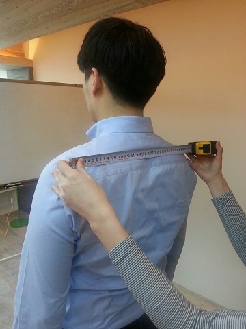
Measuring my shoulder with ruler.
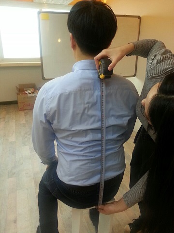
Sitted height is also very important measure that i have to consider.
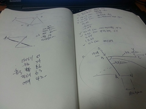
With the process shown above, leg, knee, arm, shouler length followed by sitted height and shoulder legnth I've measured the first-prototype of my project
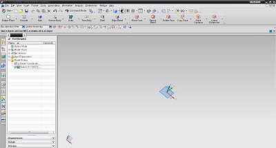
Siemens Company approvedUG-NX 7.5 Interface that i used.
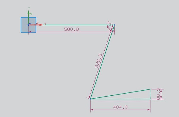
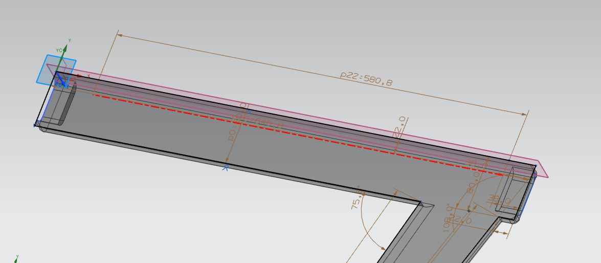
with measures i've calculated i've designed in 2-dimensions.
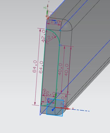
I've modeled half of the frame and the front of the part which the accessory part attach.
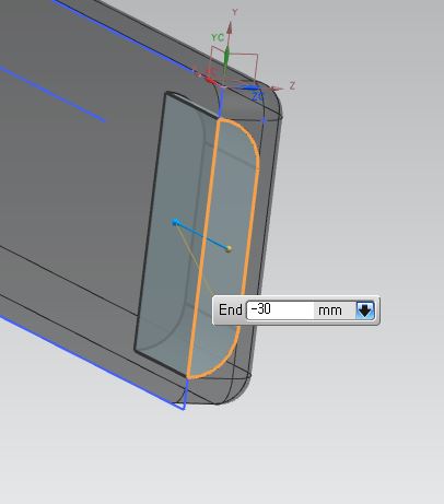
By extruding with 'Subtractive condition i've created a hole.
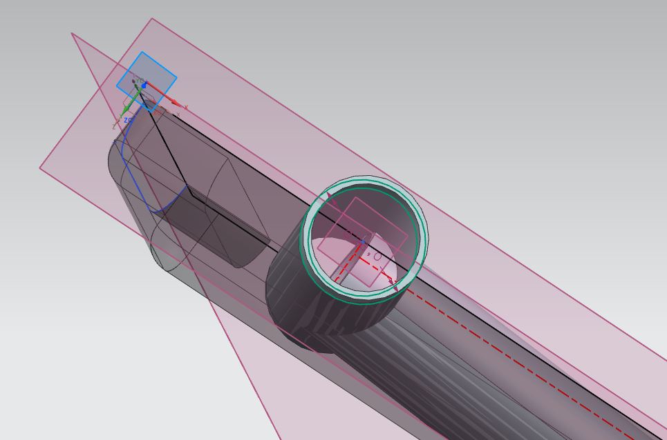
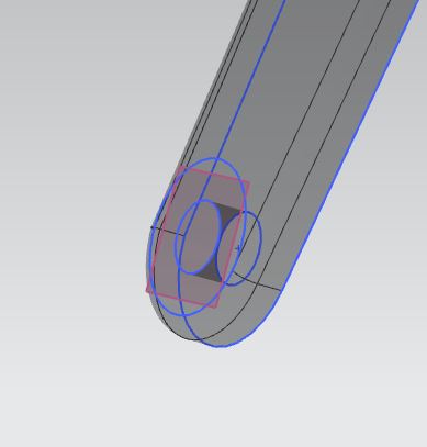
Croosrod that hold the main frame, you can see it's crooss-lined with the pipe at the front.
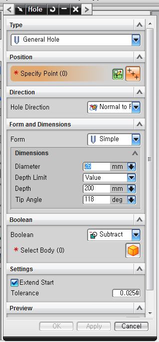
Where the pipes are intersected i used 'hole' function to clear.
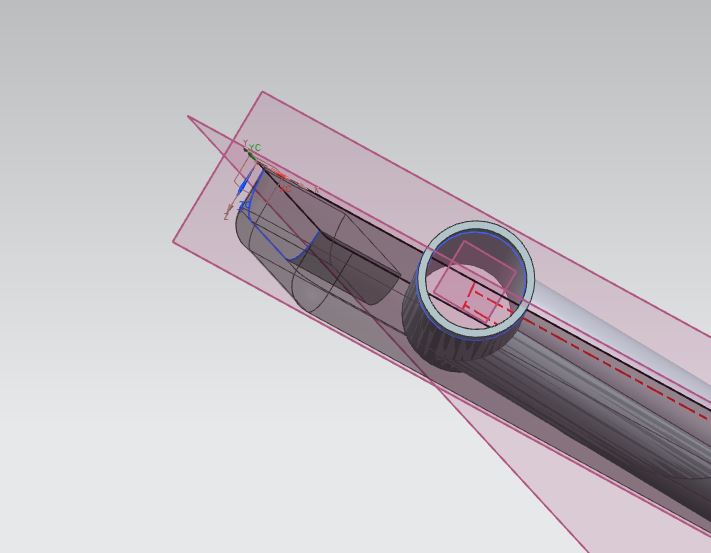
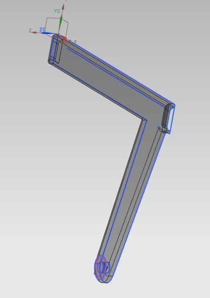
Next photo you can see my pipes are all arranged.
I fixed the distance between front-pork and seating cusion and carried on with other parts.
I've loaded main frame file to model the rear part.
Where the rear part should be created i sketched before modeling on the workspace.
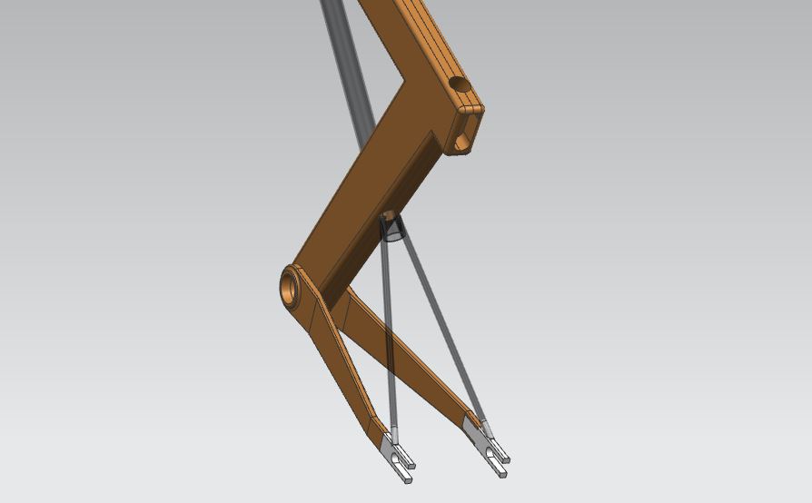
Back of the part where the wheel should be, I've architected so it's in V-shape.
Problem shown at the intersection.
Looking closely, main frame and the rear part has some gap.
Using extrude function where the main-frame and rear part are joined.
Where rear part should be joined using 'extrude' function to parallel with the surface.
Increasing strength at the intersection point. I used the trim to cover up.
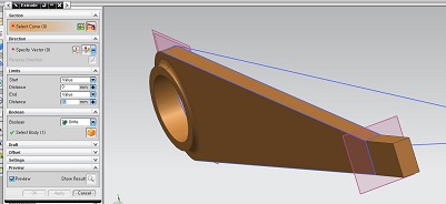
Using 'tim' function to refine the outer-design.
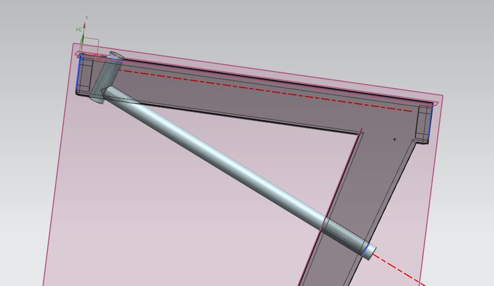
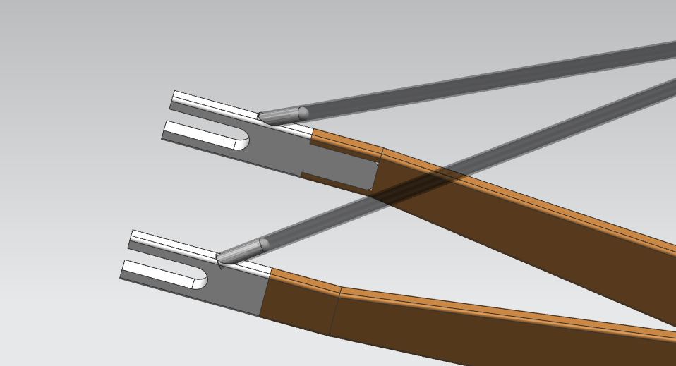
With measures i've designed the metal pipe that can stand the weight at the sitting point.
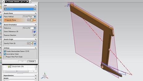
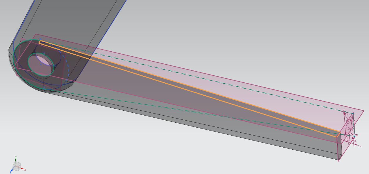
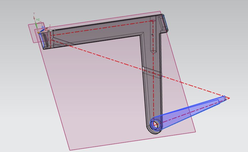
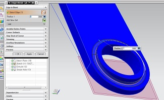
To make the metal part which holds the back-wheel i'v sketched the design rougly.
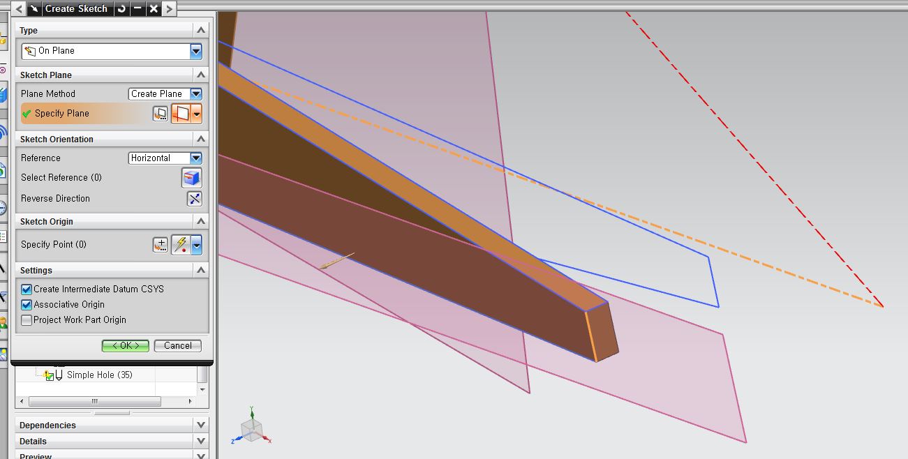
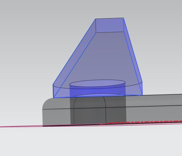
You can see it created sketch at the corner.
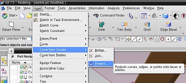
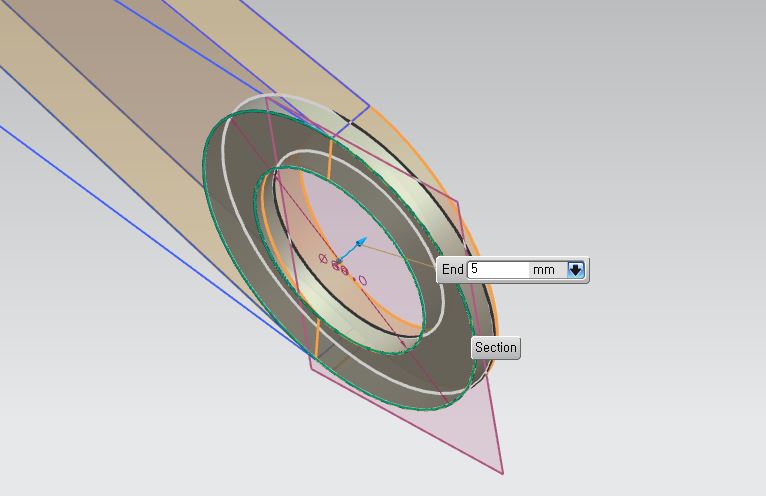
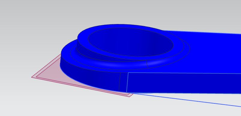
To check the center-axis of back wheel using the 'project' function I've referenced the dot i've created before.
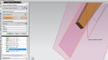
You can see the dot
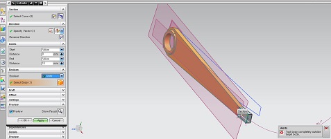
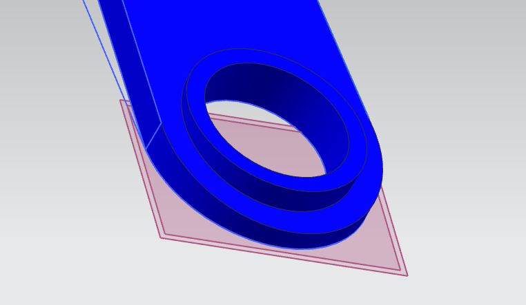
You can see the error message at the right hand corder. It meant tood body is at the outer working space with the target design. on the left when i change the Boolean from 'United' to 'None' I can extrude the design normally. But the problem is when i extrude the part like this. It can not be assembled together.
To solve this proble, I reset the surface and sketched the new rectangle to extrude the new part and finally got two parts assembled together.
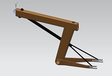
Using assembly function, I've loaded all the files i had worked on and made one 3D-modeled project. Later on, I'm planning to do 3D-modeling where the Fabduino should be inserted and other parts.
Downloads
Bicycle Measured Referenced from Homepage.
Measuring my shoulder with ruler.
Sitted height is also very important measure that i have to consider.
With the process shown above, leg, knee, arm, shouler length followed by sitted height and shoulder legnth I've measured the first-prototype of my project
Siemens Company approvedUG-NX 7.5 Interface that i used.
with measures i've calculated i've designed in 2-dimensions.
I've modeled half of the frame and the front of the part which the accessory part attach.
By extruding with 'Subtractive condition i've created a hole.
Croosrod that hold the main frame, you can see it's crooss-lined with the pipe at the front.
Where the pipes are intersected i used 'hole' function to clear.
Next photo you can see my pipes are all arranged.
I fixed the distance between front-pork and seating cusion and carried on with other parts.
I've loaded main frame file to model the rear part.
Where the rear part should be created i sketched before modeling on the workspace.
Back of the part where the wheel should be, I've architected so it's in V-shape.
Problem shown at the intersection.
Looking closely, main frame and the rear part has some gap.
Using extrude function where the main-frame and rear part are joined.
Where rear part should be joined using 'extrude' function to parallel with the surface.
Increasing strength at the intersection point. I used the trim to cover up.
Using 'tim' function to refine the outer-design.
With measures i've designed the metal pipe that can stand the weight at the sitting point.
To make the metal part which holds the back-wheel i'v sketched the design rougly.
You can see it created sketch at the corner.
To check the center-axis of back wheel using the 'project' function I've referenced the dot i've created before.
You can see the dot
You can see the error message at the right hand corder. It meant tood body is at the outer working space with the target design. on the left when i change the Boolean from 'United' to 'None' I can extrude the design normally. But the problem is when i extrude the part like this. It can not be assembled together.
To solve this proble, I reset the surface and sketched the new rectangle to extrude the new part and finally got two parts assembled together.
Using assembly function, I've loaded all the files i had worked on and made one 3D-modeled project. Later on, I'm planning to do 3D-modeling where the Fabduino should be inserted and other parts.
Downloads
Makers Gonna Make !