Fab Academy 2015, Dong-Hyun Kim
Input Devices
Redesign an Input board
I plan to make switch to input device, and it is for my final project.
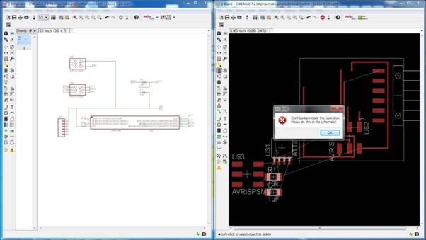
My design is based on Hello.Button.45 in Fab Academy Archive I studied it and redesignit.
I try to remove the connection from Board screen the software show me some warning sign. Which was “Can’t backannotate this operation. Please do this in the schematic!” and it means you can’t erase the connections from Board screen. You can modify circuit only on Schematic screen. So, I got back to Schematic screen to erase the connection and I connect it on Board screen.
‘Can’t backannotate this operation. Please do this in the schematic!’
Components
Mill the board and soldering
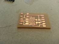
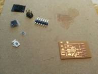
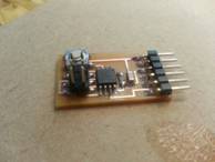
The board I made was well soldered and cut well.
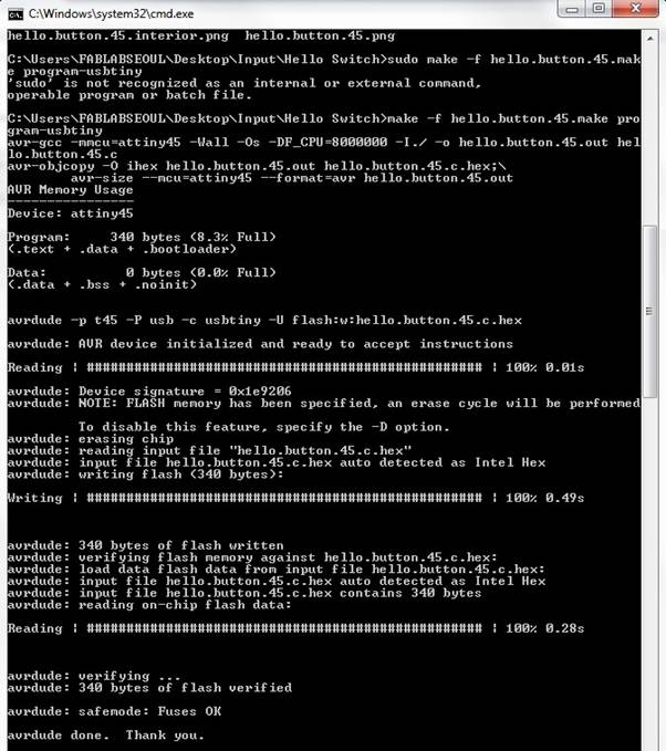
Use “Make” file to upload Bootloader on ATTiny45. It is worked well.
Program a board (with Arduino IDE)

I programed it by modifying the sample code and I success programming to make LED on when I keep push the button and off when I put my finger off from the button.
Button Switch Serial Monitoring
You can see when I bend flex sensor, sensing value change from 84 to 224 in serial monitor.
These value are analog value, we can use digital out put with map() funtion.
What is flex sensor
Flex sensor can measure how much bended. It is kind of resistor.
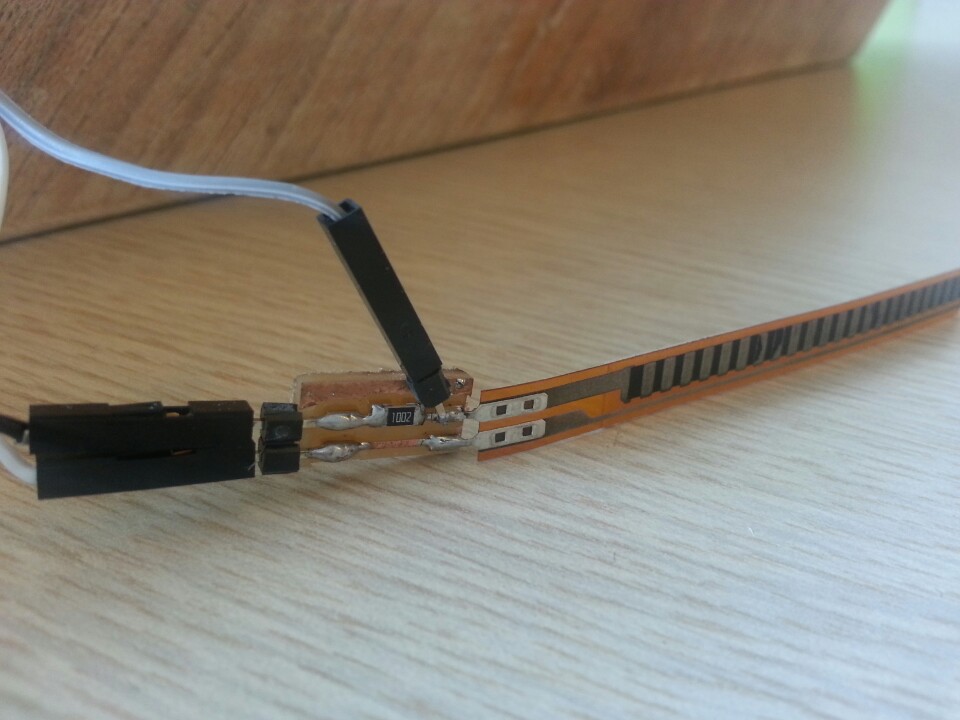
Design felx sensor board
Trouble shooting
When I look serial monitor in Arduino IDE, That shows me that unidentification words, So, I chage the Clock to baordrate 9600. then it works.source code
int flexpin = A5; |
Flex Sensor Serial Monitoring