Week 4: Electronics Production
-
2015-03-05. Even though this week's homework is already a week and a half overdue I am not yet finished. I ran into numerous problems with the Roland MDX-40A CNC machine in our Fablab.
-
I found and attempted to follow this tutorial for milling circuit boards with this machine.
-
Aside from generating the .rml file using fabmodules, I also needed to run it through a Python script to multiply the distances by 2.48. Because the only copy of this Python script that I could find was in the tutorial PDF file, I had to copy and paste the script into a text editor. Unfortunately, when copying text from PDF files using Adobe Reader, all tabs are lost. Unlike most programming languages, tabs are an essential structural part of Python code, so I had to go through the program line by line and indent as necessary. I suppose I was in too great a hurry and accidentally indented an "if" statement that I shouldn't have, which resulted in the script exiting it's line reading loop on the first line and not processing anything. I struggled for an embarrassingly long amount of time with this problem, thinking that there was something inherently wrong with the original program. I tried changing all the "\n"s in the .rml file to "\r\n", I tried changing the regex that found lines that needed modification, I tried forcing it to change all lines whether or not they needed it. Finally I took the time I should have taken in the first place to analyze the program structure and quickly found my problem. An extra tab. Okay, that problem was out of the way.
-
We had a Windows 7 computer with two programs set up for interfacing to the machine. One was VPanel which allows setting user coordinates of x, y, z and a (a being the angle of the device that holds milling material and can rotate it vertically on a horizontal axis). I figured out how all this worked in very short time. The other program I had been trained on was for milling 3D objects but didn't seem to have any feature for opening or importing .rml files. The tutorial's instructions for sending the .rml file generated by fabmodules required using CUPS on linux. I attempted to work around this by searching online for some kind of software to send .rml files to a Roland CNC machine, but turned up nothing. I attempted setting up a generic printer on Windows using the RAW printer driver and sending the text in the .rml file, but just got printer errors. I attempted using Window's notepad program to write the .rml file to the MDX-40A "printer", but only achieved milling the text of the file onto the cardboard I had set up for initial testing (it was a makeshift set up; as you'll soon learn setting up a board to be milled was not to be so easy). Finally giving up on finding a way around using linux, I set up Ubuntu in VMPlayer on my laptop and continued to follow the tutorial.
-
I set up the CNC machine as a printer in CUPS without too much trouble, in accordance with the tutorial. When I printed the raw .rml text file to the printer, it began milling the circuit board pattern on the cardboard. I was initially delighted to think that I was finally done solving problems. Then the machine stopped halfway through with the bit still spinning. After waiting a reasonable amount of time I reset everything and started over again, only to have it happen again at the same place and same time. I tried re-generating the .rml file using fabmodules with some slightly different parameters, but got the same results. I tried not running the 2.48 multiplier Python script with the idea that it was possibly generating some erroneous value in the .rml file, but all to no avail. When I went back to Windows and ran VPanel, it reported that the machine had stopped with an "RML Command Error". I spent no small amount of time reading through online search results for this error, but found nothing that addressed my problem. I began poking around in VPanel to see if there was anything I might be able to change about the device's settings that might make accept the .rml file and finish the milling job, when I happened upon VPanel's "Cut" feature. To my astonishment, joy, and annoyance, I discovered that I could simply send .rml files directly to the MDX-40A via VPanel in Windows! Well, a lot of time had been wasted when a solution had been almost right in front of my eyes from the beginning, but at least I was beginning to see light at the end of this very long tunnel. Or so I thought.
-
The Roland MDX-40A Precision Prototyping Milling Machine in our lab comes with a wonderful accessory called the ZCL-40A Rotary Axis Unit:
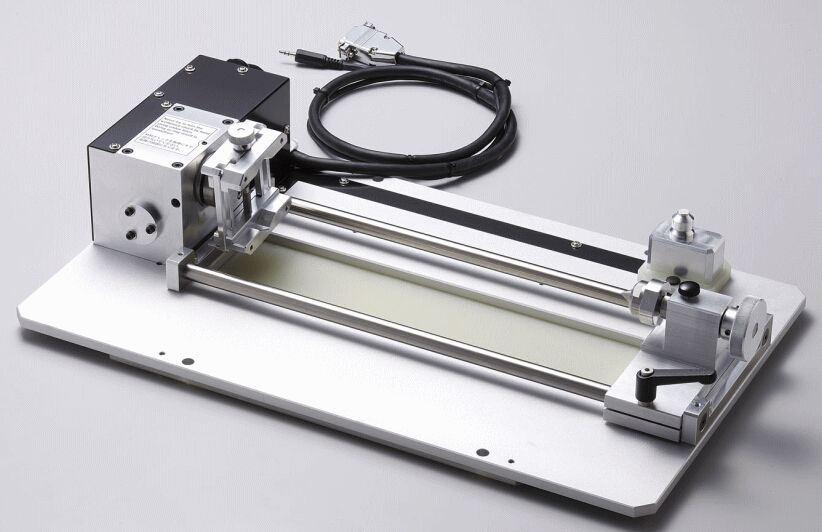
It is great for milling in 3D, and also great for preventing me from having a flat bed on which to place my circuit board for milling. I was working alone at Fablab in the dead of the night at the time, and didn't want to attempt to remove this accessory without permission from the management. I thought I had a fairly simple solution. Just place a flat object in the rotary axis unit's vice, attach my board onto the upward facing surface of that object, and set the A axis (the rotary axis unit's angle) to zero. I found an elongated rectangular solid of some kind of red foam, the center of which had been previously milled out, to make a model of a cell phone. I wanted to find some small clamps to clamp my board onto it, but couldn't find anything resembling clamps in the lab. I did find some double-sided tape and used that instead. The clamps would have made things much easier as my board was not entirely flat. It tended to curve up slightly at the edges and corners. Clamping it down would probably have made it a lot flatter and avoided milling problems with the depth differences caused by that curvature. But I would have to try to make do.
-
Much to my surprise and mild horror, zero degrees on the rotary axis turned out to be nowhere even close to resembling flat. Looked more like about 30 degrees or so. I couldn't find a protractor to measure the angle. I searched online to try to figure out what that angle was so that I could turn it back by that many degrees, but no information was forthcoming. I thought of using a bubble level to make it level, but couldn't find one anywhere. Then I realized that wouldn't help much anyway, because it would only help me level it on a tangent line perpendicular to the force of earth's gravity, not perpendicular to the Y axis of the milling head's movement. With no reasonable solution at hand and a brain growing increasingly incompetent for lack of sleep I chose what I knew to be a far less than ideal solution to solve this problem. First, using my eyes only as a guide, I set the rotary axis unit as flat as I could determine. Second, unable to find a ruler, I used a post-it note and marked the distance from the motor housing unit to the surface of the upper face of its vice grip at the end nearest me. I then proceeded to use this distance mark to check the distance at the far end. I carefully adjusted the rotation angle back and forth several times, measuring each time, until it seemed that I could achieve no higher precision of "flatness" using this method. Fourth, I set the milling bit about a millimeter above the circuit board near the near edge and loosened it until it fell to rest on the circuit board face. After re-tightening it I used VPanel to very slowly move the bit toward the far edge of the board. When I could see that it had begun scraping at the copper, I knew that the far edge must be ever so slightly higher than the near edge. After going back and forth several times using this so-called "calibration" method I got the board as flat as I thought I reasonably could. After all the board I was milling looked to be at least 1mm thick, so I figured I had at least a 0.5mm error margin.
-
Finally! I could begin milling my circuit board. I didn't have my hopes up too high about getting it right on the first try, so I wasn't disappointed when on the first two tries the bit chewed through the copper traces that it should have left.
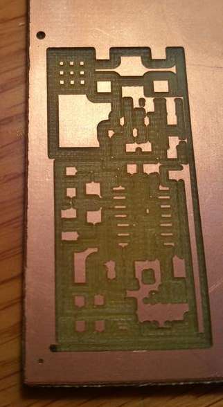
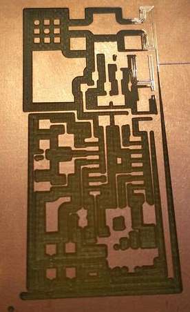
But after hours of trying and wasting copper clad board I came to the conclusion that the 0.5mm diameter milling bit I was using was just too big. Of course the very tip came to a sharp point and therefore if I just barely used the tip for milling it was narrow enough. The problem was that my board wasn't completely flat. I actually found that the process I used above to "flatten" it by finely adjusting the rotary unit might have been largely irrelevant since the board itself had a slight curve, being lower in the center and higher toward the edges and corners. No matter what I did, the tip of the bit would either go all the way in to the high parts so that the full 0.5mm would be used and mill through some of the traces, or not go in far enough to mill through the copper, or even worse not touch the copper at all, on the low parts. Or sometimes on some runs both would happen on the same little milling area.
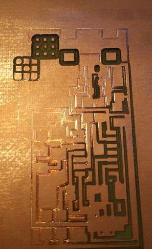
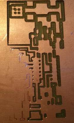
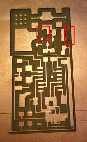
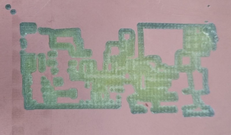
I almost got one right by milling near the center of the copper board, but even that had two places (outlined in red in the image below) where the what appeared to possibly be a conductive trace was indeed too eaten away to pass current after all. I confirmed this with a continuity test using a multimeter, which I was pleased to find on hand in the lab.
-
Despite my persistent failures I was determined to do whatever I could to mill a useable circuit board before I had to leave for work. Time was getting short and I hate having to stop working on a task without having at least achieved partial satisfaction. Sure, I knew that I would still have to mill the circuit board borders through in order to cut it out of its copper board, solder all the components, and program the ATTINY chip, and that there was no way I would have time for all that before work, but I still wanted to get the circuit milled before I quit if at all possible. I decided to try to slightly adjust the angle of the board in the rotary axis unit in an effort to make an area between the middle of the board and one edge of it "flat", perpendicular to the milling head's movement on the y axis. I went back to my method of slowly moving the head near and far across the board while checking for scraping and making tiny adjustments to the rotary angle. VPanel has several speed settings when using it's controls to move the machine's axes, ranging from .001 millimeters per click to 1cm per click. I was usually using .01mm per click (or .01 degrees when adjusting the rotary angle), but used the 1cm per click speed to reposition the head in a new location for another "drag" test across the board. That's where I made a terrible mistake and forgot to switch the speed back to 0.01 before clicking to raise the angle of the rotary unit. I clicked and the unit tried to rotate an entire degree instead of .01 degrees, which push the copper clad board hard into that little 0.5mm head and broke it.
-
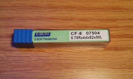
After that disastrous development I was nearly out of hope of having anything to show other than having learned what didn't work for my long night's labors. I found the next smallest milling bit we had, 0.75mm and without much hope tried a run with it, but it was immediately clear that there was no hope in using it. Half a millimeter was already too big under the circumstances. I needed something thinner, not thicker. And so with a heavy heart I set about doing what little I could with my time.
-
I went to our collection of components for the circuit and started identifying and setting aside for myself two of each since I was planning on doing the soldering at home, and wanted some components in reserve in case I destroyed any by accident. The surface mount resistors were so tiny I couldn't read the numbers printed on them without a magnifying glass, which I didn't have. I did manage to identify them by measuring their resistances with the multimeter, and wrote the values on the backs of the packaging strips in order to help future students or myself next time I needed these. The capacitors had some scribbling on the back of their strips. It wasn't too easy to make out the markings, but since there were only a few different values I needed, I think I was able to identify them correctly. I don't know how to use a capacitor tester yet so I wasn't able to find out empirically. If my circuit doesn't work after it's all soldered together I'll have to consider that my capacitors might be mixed up. There's nothing printed on them at all, so I don't know how I will figure it out if it is a problem. One of the resistor values I needed was also available only in conventional through-the-hole type, not surface mount. The same was true for the 20Mhz crystal. The 6 pin header and connector were missing altogether. I made a list of what was present, what wasn't, and what was wrong or ambiguous so that I could inform our class facilitator.
-
It is now March 6 and our class facilitator and his assistants are working on getting us the milling bits and the remaining electronic components that we need in order to complete week 4's assignment. When the new bits arrive I will begin to try again, and hopefully achieve success this time without discovering too many more problems!
-
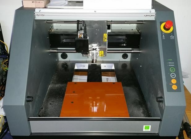
2015-03-11. Tonight I successfully removed the ZCL-40A Rotary Axis Unit from the MDX-40A and installed the machining bed/platform:
-
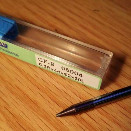
I then happily proceeded to open the package containing what I expected to be new 0.3mm milling bits, believing that I could finally mill my circuit board and proceed to finish the assignment. But when I saw the new milling bits, I knew immediately that something was wrong:
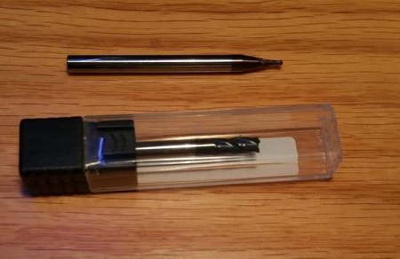
The picture above shows our existing 0.75mm milling bit with what was supposed to be 0.3mm milling bit below it. Obviously, the new bit is far larger than 0.3mm. Is it 0.3cm? Probably bigger. Maybe 0.3in? I can't tell for sure, and since I expect fablab will want to return it for a refund or exchange, I didn't want to break the seal, open the case, and measure it.
-
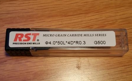
I compared the 0.75mm bit label to the new bit's label, and could see that some of the markings were different, but have not yet done the research needed to understand what went wrong when choosing which bit to buy. The new one does say 0.3, it just doesn't say in any way clear to an unfamiliar eye that it is 0.3 of what unit. So, for now this assignment is still on hold :-(
-
Despite knowing that I would not be able to successfully mill the circuit board, I wanted to go through the process and make sure there weren't any other problems now that I'd removed the rotary unit and installed the bed. I set the X, Y, Z origins to the surface of the board, whit the 0.75mm milling bit protruding perhaps 1cm from the spindle. I recreated the .rml file from fabmodules.org and ran it through the python script, and tried milling it. Although I had set the jog height to 3mm in the fabmodules, the spindle always got pulled up to about Z = 0 on the machine coordinates (not user coordinates), and then very slowly descended back to the board. At that rate milling a small board would take days, so it wasn't acceptable. I attempted to remedy the situation by setting zmin = -104.73 when creating the .rml file from fabmodules, and it almost worked. The only problem was that the bit wouldn't go down any further than my user coordinate Z=0. After much trial and error I discovered that if I just let the bit out of the spindle another centimeter or two, so that the user coordinate Z=0 was greater than machine coordinate Z=-100, everything was fine. I was then able to use the too-large 0.75mm milling bit to successfully test milling a circuit board. As expected, the bit was way too thick and ate away nearly all the traces, but at least the mechanism is set up to work now, if I can just get the 0.3mm bit I need:
-
-
I will continue to update this page when I am able to proceed with this assignment.