
13 -
Networking and communications
The goal of this assignment is that design and build a wired &/or wireless network connecting at least two processors.
In this week, the original intention for this project was that I want to try IR communications between 2 devices. I modified the board I designed last time (Output devices), and added IR transmitter and IR receiver to each board.
I changed the design a little bit because I think the board may be used standalone, so I added a 5v voltage reguator (PJ7085). Regulator is the components I've not tried before. the regulator may need to connect a DC jack. I added a 2 pin header space for DC jack.
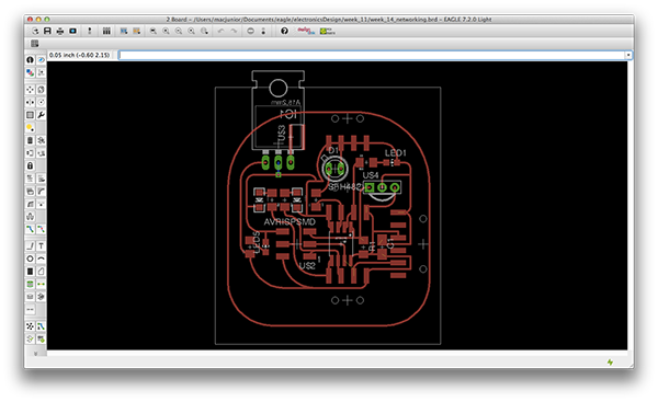
source files: week_13_networking / week_13_networking (Note: this is not the one I use in the 2nd, and 3rd experiment).
The 1st Experiment: IR connections
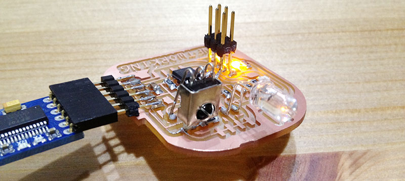
The goal is to let 2 devices communicate to each other, so I milled two exactly the same board at the same time.

After soldering all the components and connecting to the power supply, the board seems OK. but I found that there is a small mastake on DC jack's 2 pin header.
My idea is that those 2 devices can communicate like the picture I showed below. One can transmit a message to the other, and the other can deliver a feedback iteratively.


There were some problems I still can't solve:
1. both of IR transmitter were unable to set HIGH voltage.
2. Unable to use IR library.
3. is there synchronize problem between 2 devices?
The 2nd Experiment: I2C library
Since wireless connection can not be established, I started to try something with wire. There is a I2C libiray for attiny on arduino website, and also Aser from Fab Academy 2014 provided a very nice tutorial about I2C. I follow those 2 reference and build my own system:
1. desoldering some parts. At last IR transmitter and IR receiver.
2. adding wires between Tx, Rx between my board and FTDI. Acctually this was a small mistake I made in 1st version design. I should directly connect Pin 0 to Tx and Pin 1 to Rx, so that I can simply assign Pin 0 as Rx, and Pin 1 as Tx in SoftwareSerial.
3. Using Software Serial libray for serial communication between one of my boards to my computer.
4. Connecting SDA, SCL with 2 wires.

Honestly, I didn't get it done. Although IDE consol printed something which mostly what I want, there were some gibberish.
The 3rd Experiment: SoftwareSerial
This is the assigment that really made me feel frustrated, because all I tried above was not successful. In order to solve it, I need to minify the scope. Finally I used SoftwareSerial Libray only to get it work. My goal of the 3rd experiment is establishing a very simple connection using .write() and .read() function.
What I did:
1. Set Clock > 8 MHz (internal) in Arduino IDE and burn bootloader again.
2. connect board A and B's tx, rx pins. Pins can be customized defined in program. It's not necessory to follow my pin definition.
board A:
// board A
#include <SoftwareSerial.h>
SoftwareSerial boardSerial(3, 4); // rx, tx
#define sendByte (byte) 0
void setup() {
//mySerial.begin(9600);
boardSerial.begin(4800);
}
void loop() {
boardSerial.write(sendByte);
//mySerial.println("sent");
delay(20);
}
board B: mySerial is a pairs of pins to connect my computer. And boardSerial is for boards communication.
//board B
#include <SoftwareSerial.h>
SoftwareSerial mySerial(0, 1); // rx, tx
SoftwareSerial boardSerial(2, 4); // rx, tx
byte inByte = 0;
int buf;
void setup() {
pinMode(3, OUTPUT);
boardSerial.begin(4800);
}
void loop() {
if(boardSerial.available()){
inByte = boardSerial.read();
buf = buf*10;
buf += (int)(inByte -'0');
mySerial.println(buf);
digitalWrite(3, HIGH);
delay(1000);
digitalWrite(3, LOW);
delay(1000);
}
}
The communication was done as the picture shown below. board B's led can blink when it was set correctly.

correct trace:
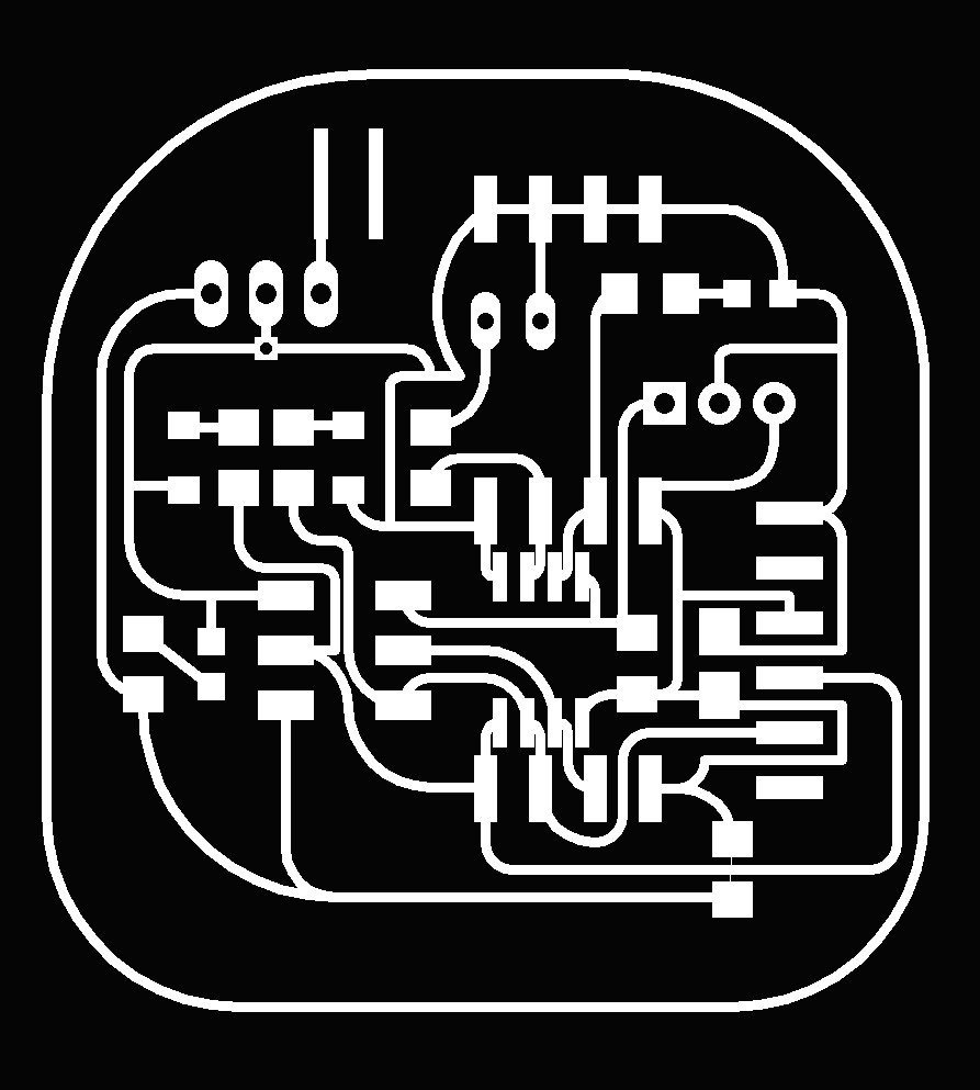
source files:
Demonstration:
:)