06 -
electronics design
Electronics design week is not easy for me. The first challenge is that although I have used Frizing in my thesis, Eagle is an advance tool for me. The other challenge is trying to find correct SMD in Eagle library.
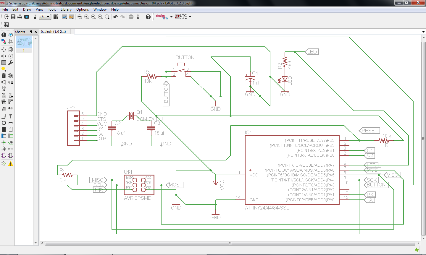
In Eagle, I can simply add lable to each component or line (wire) in scheme, component will connected its corresponding pin. Some of the green lines in the picture below, may not necessory to link to each other, but for visualization, I prefer to add the lines instead of only showing labels.
I don't have 20 mhz resonator so I use 1 crystal (20 mhz) and 2 capacitors (18 uf) instead of resonator.
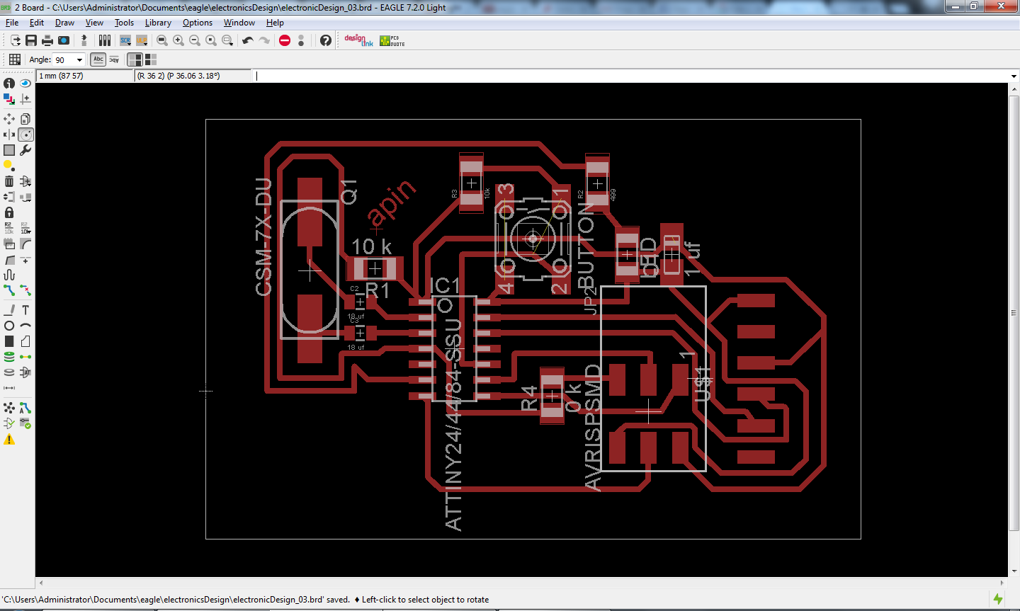
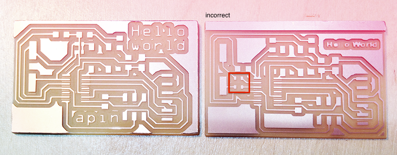
I maked 2 boards this week. The 1st one is incorrect because I made a mistake on connecting 18 uf capacitors.
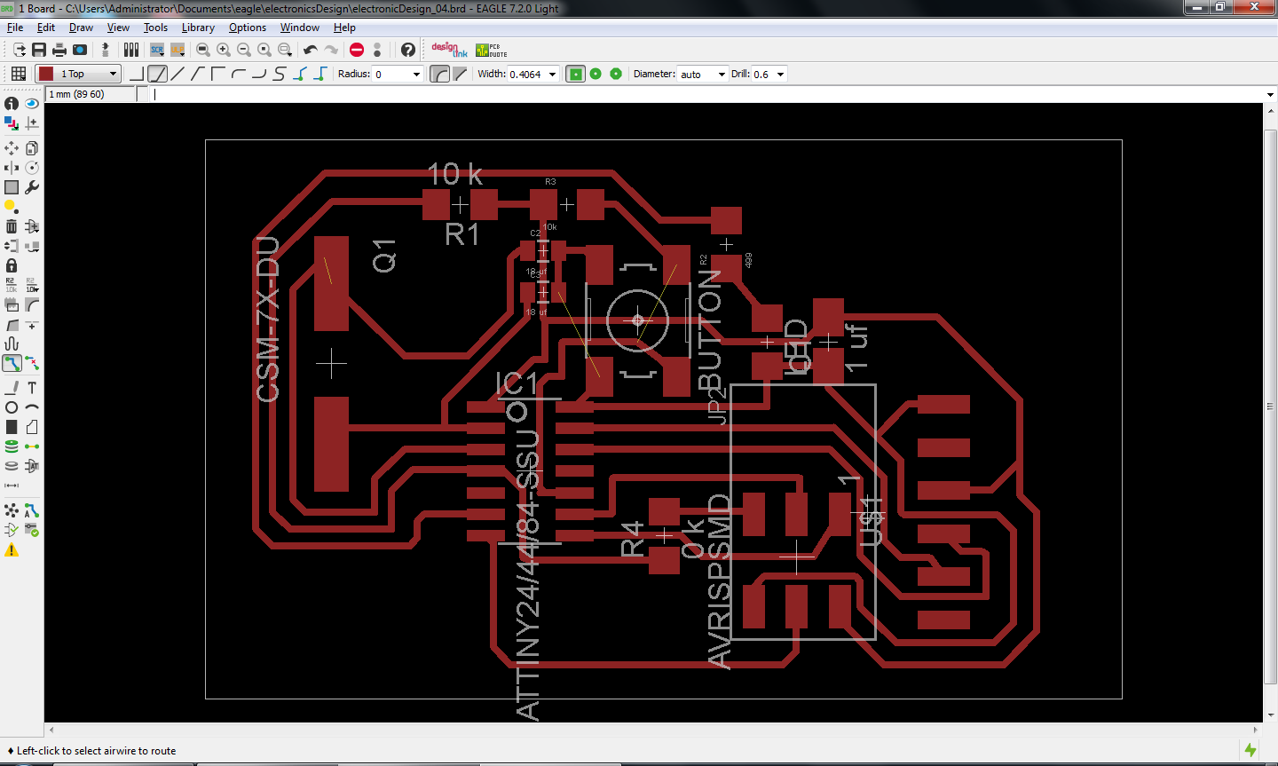
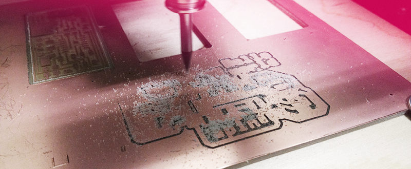
After I milling the board, I found out the error in a discussion. Therefor I changed my layout and milled again.
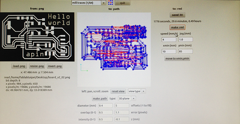
Here is fab module setting. The default setting of offset(-1 to fill) is 4, but I changed it to 5.
The board in right hand side is incorrect. There are 2 erros:
1. 18 uf capacitors' are connected to wrong pins.
2. The height of board is incorrect. It seems that I scale in fab module but I did not notice that.
Part list:
- Attiny 44 x 1
- 20 mhz crystal x 1
- 18 uf capacitor x 2
- 1 uf capacitor x 1
- 10 k resistor x 2
- 0 k resistor x 1
- 470 resistor x 1
- button x 1
- Led x 1
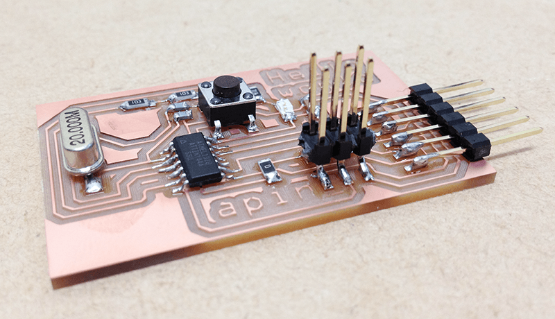
The result:
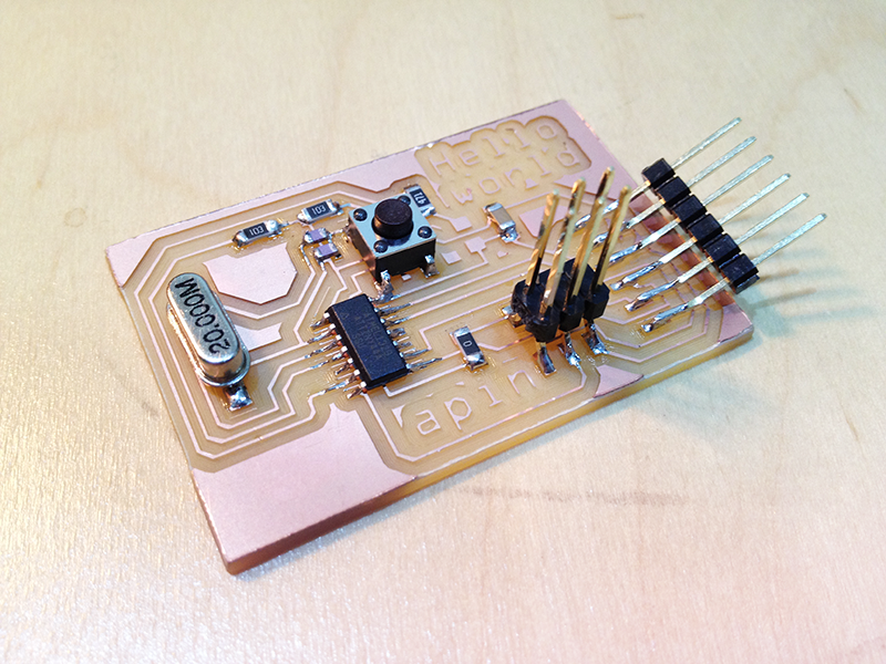
the connectors are so weak:
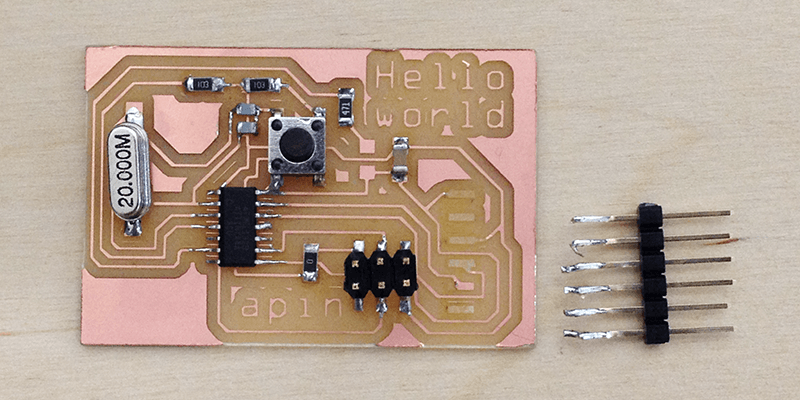
therefore I made another one to modify the angle of connectors.
Source files:
.sch file: electronicDesign_04
.brd file: electronicDesign_04