Design
As the rotor is the core of the device I am designing the rest of the mechanism around it, Ultimately the device is designed for free stand but also be capable of mounting on a wall using something like DIN rail to make assembling larger dispenser systems practical.
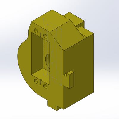
Pillow Blocks
The pillow blocks support the rotor by way of 608ZZ ball bearings and are in turn held in place by the baseplate, the 2 pillow blocks are non-symetrical, both due to the flat rear surface for attaching to a rail and one of the blocks has been modified to mount the servo motor.
Rather than modeling both separately, I made use of Solidworks 'Configurations', whereby I am able to apply certain features to only one 'configuration' of the model, when it comes time to insert the part into the assembly the configuration used for each instance can be selected.
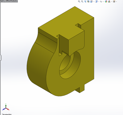
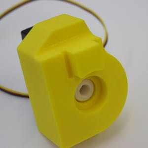
The Motor Mount
One of the pillow block configurations has been modified to mount the servo motor that drives the rotor, this involved creating a much thicker part in order to accommodate the motor and the added length of the rotor drive shaft.
The servo motor is designed to mount using 4xM4 bolts, by making the holes slightly interfere the bolts essentially self-tap into the ABS holding it firmly.
Hopper
The hopper is designed to feed the batteries to the dispensing cylinder, preferably without jamming or otherwise becoming blocked. For simplicity for this first prototype I have made it a single file hopper making it much less likely to jam.
Version 1
Version 1 was a simple tab & slot construction open ended box that slotted into the pillow blocks at the bottom to hold itself together. It was retained at the top by a pair of M3 bolts with nylock nuts. Unfortunately I had underestimated the effect the force exerted by 20 batteries in a stack would put on the sides of the hopper. The result was that when fully loaded the sides of the hopper tended to push apart slightly causing the hopper to widen and for the batteries to jam, this was sub-optimal.
Version 2
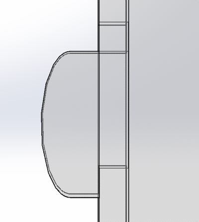
Version 2 replaced the 2 M3 bolts with a series of dog-leg catches on each of the tabs, the result being that rather than a span of ~20cm of flat PMMA being unsupported against the force of the batteries pushing out the longest span going unsupported is now 47mm.
The result of this modification was a far more reliable battery feed, not only during the dispensing but also during the loading of the hopper, previously the looser sidewalls when pushed out allowed the batteries to tumble when being fed into the dispenser, now they go in like a dream.
Drive Coupler
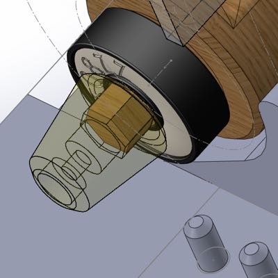
The drive coupler is designed to interference fit onto the servo drive spline on one end and have a tightly toleranced but non-interfering fit onto the hexagonal drive shaft of the dispensing rotor.
The 3D printers we have available in the lab are not accurate enough to properly reproduce the spline on the servo however I can exploit the lower density (Nylon and ABS have similar thresholds for plastic deformation but the lower density due to the 3D printing process makes the difference) of the 3D printed ABS as compared to the nylon spline, by forcing the slightly interfering coupler hole onto the spline the nylon causes a plastic deformation in the 3D printed part imprinting the desired spline pattern.
Internally the drive coupler has provision for the use of the servo horn retaining screw used on the servo, I have found it largely uneccesary during testing as the structure of the mounting instelf keeps the spline compressed into the coupler.
Fabrication
3D Printing
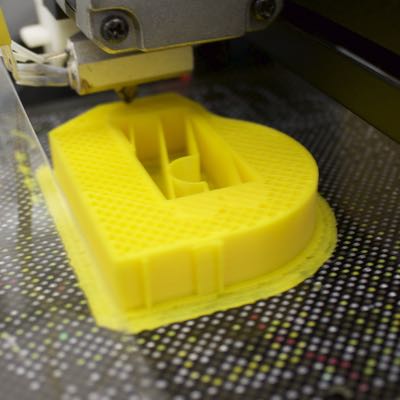
I have used 3D printing to produce the more complex geometry of the pillow blocks, both were designed specifically for 3D printing and minimise overhangs where possible. Where overhangs were unavoidable I have oriented the print to require support only in the areas where dimensional accuracy was less important and kept them relatively large to facilitate easy removal of the support material.
The servo drive coupler has also been 3D printed however I opted not to print it simultaneously with the pillow blocks, the coupler required more dense infill and different support settings to optimally print and unfortunately one shortcoming of the PP3DP UP! software is that it is not capable of assigning different print settings to different models within the same job.
Lasercutting
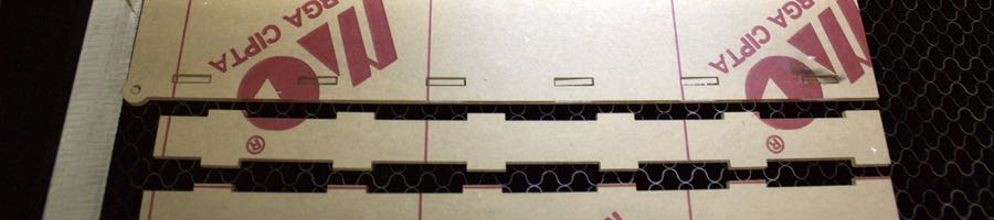
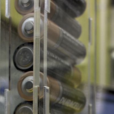
The hopper for this dispenser module is designed to be lasercut, I opted to use 3mm thick PMMA (Acrylic) sheeting which has enough strength to hold the required load as well as being relatively inexpensive. This comes with the added bonus of actually being able to see the products in the hopper.
You can see in the image above of the V1 hopper being cut, there is a slightly blackened area around the hole at the top right of the image, this is due to the laser starting to cut without the compressed air assist being turned on which is in turn caused by me being an idiot. I have modified our laser to use the shop air available in the lab in lieu of the small compressor however I have had 'connect compressed air to solenoid valve run by laser control board' on my todo list for the many months since, currently I believe it is #1.724x10⁷ on that list. I will do it eventually.
Assembly
Now comes the fun part, time to put all the pieces together
Step 1: Installing the Servo Motor
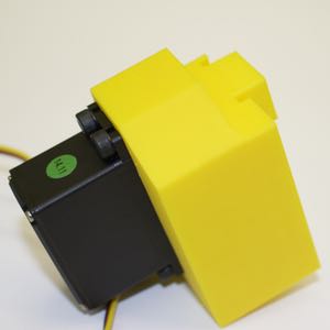
The first thing to do is to install the servo motor into the motor mounting block, it's at this point one gets to discover the dimensional accuracy of the 3D printers used, fortunately in my case it was pretty good and the motor went in with a snug fit.
The interference fit with the M4 bolts worked perfectly with the bolts holding well with only minimal effort to self tap them into the block, Rigorous testing demonstrated that the bolts were indeed well fastened into the block.
Step 2: Installing the Drive Coupler
Installing the coupler can be done from the rotor side of the motor mount block, the coupler can simply be forced onto the servo spline and the retaining screw installed if desired, ultimately the coupler will be sandwiched between the rotor bearing and the motor so the screw is not strictly necessary.
Step 3: Installing the bearings
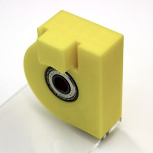
The bearings are designed to press fit into the pillow blocks, these are 608ZZ skate bearings, readily available from pretty much any bearing or skate shop. I've attached the support block to a piece of acrylic to act as a structural support for the purposes of testing this module.
Step 4: Installing the Rotor
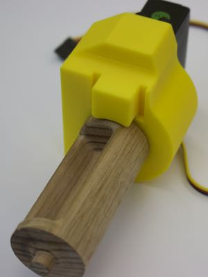
Once the bearings are in place it's time to slot the rotor into the drive block, if everything has been fabricated to spec the hexagonal drive shaft should push easily into the drive coupler behind the bearing.
At this point I tested that the coupler was properly engaged with both the servo and the rotor by gently turning the rotor by hand and listening to the servo move, it had almost no backlash whatsoever which made me quite happy.
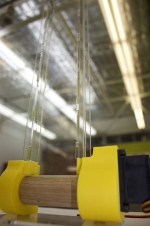
Step 5: Joining the Halves
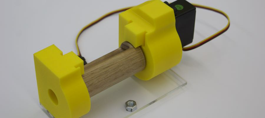
Once both halves have all their sundry bits and pieces attached it's time to put them together, once they are fastened in place they whole mechanism becomes rigid, It's at this point that I tested the motion of the servo and checked that the rotor moved correctly when it was actuated.
I did notice one slight oversight on my part, when I had installed the rotor I had not lined up the home position of the servo with the desired home position of the rotor, I opted to correct this in software with a configurable 'rotor home' setpoint rather than disassembling the whole thing at this point.
Step 6: Installing the Hopper
And finally, the final component, the hopper gets installed. The hopper sits in the slots built into the 2 pillow blocks, the hopper itself holds 20 batteries and is held together by built-in clips (Not shown in picture, that's V1 which used 2 bolts at the top).
The hopper should line up perfectly with the pocket in the rotor, if it doesnt then the servo home position can be trimmed in software.
Does It Work?
It Works! The servo actuates the rotor perfectly and a rate of roughly 2 batteries per seconds can be achieved.