Press Fit Kit
Design
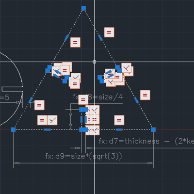
Continuing on with my theme of Parameterise All The Things! I decided to give AutoCAD's parametric functionality. To that effect I created
'kerf'
The amount of material removed by the laser when it cuts, this parameter effects the offsets applied to both the overall shape for dimensional accuracy and to the slots to compensate for the lost material and maintain a good friction fit.
Based on some testing with a feeler gauge we have determined the kerf on out LG500 in clear acrylic to be approximately 0.2mm.
'thickness'
The thickness of the material being used to make the press fit construction set, used to set the size of the slots.
'size'
The overall size of the parts for the construction set, for square parts this is the size length, for circular parts the diameter and for triangular pieces the perpendicular distance between the centrepoint of each side and the centre of the triangle.
Cutting the Parts
Machine
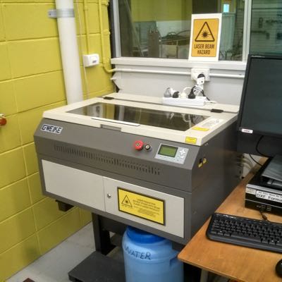
The lasercutter we have in the FabLab is a G.Weike LG500 CO2 machine, it has a maximum optical power output of 80W and a working are of 500mm x 300mm.
This is the oldest piece of equipment in the lab (it predates the FabLab and my employment) but it has performed venerably. For what these machines cost they are brilliant, they don't have the ultrafine engraving ability that the Trotec and Epilog machines do but for around 10% of the price I can't complain.
We have a table of settings for the LG500 and so before cutting I confirmed the settings for 3mm clear PMMA which gave a maximum cutting speed of 15mm/sec with power at 100%, I slowed the laser down a little bit to 12mm/sec as it has been a few weeks since I last cleaned the lenses.
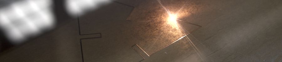
Performing the Cutting
The cutting took approximately 4 minutes to cut out the 3 different test shapes. We normally cut with the protective paper or polymer left on the PMMA sheeting to prevent it getting scuffed or heat damaged on the underside, I have heard some reports that the paper on these has caused issue for some labs but we've never had an issue.
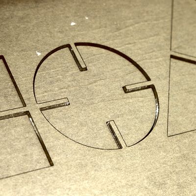
Lets Test the Fit
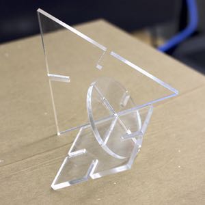
Success! The parts fit together more or less perfectly, I could probably have adjusted the kerf compensation down a little bit as the parts were quite stiff going together.
I would quite like to continue my experimentation with some extra shapes once I have a bit more available time.
Compost Lab
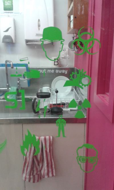
To get some practice on the Vinyl Cutter the FabLabWgtn FabAcademy class resolved to decorate the 'Compost Lab' with custom vinyl decals on the transparent curtains separating the compost lab from the Shopbot area.
Thanks to Australians having something of a reputation for being overly obsessed with OH&S I decided to create a decal consisting of a collection of warning signs, I already had these in vector format from making smaller stickers for a few machine builds I did back in Perth.
Design
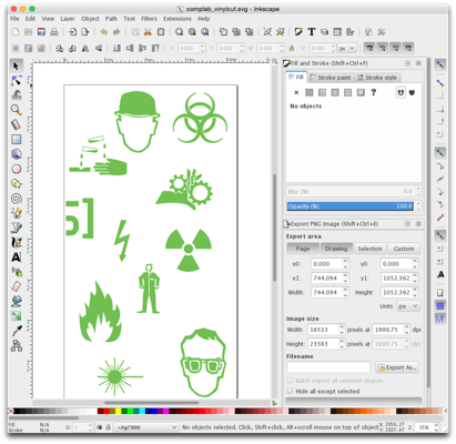
I chose to use Inkscape to create the cutting files, the template file was supplied by Wendy in Adobe Illustrator format, after a bit of mucking around I convinced Inkscape to import the file properly and set about bringing in the symbols from other SVG files.
I did have to modify some of the symbols as they were originally constructed solely for on-screen display purposes and were not correctly formed for cutting, I spent about an hour getting everything to be clean paths in Inkscape.
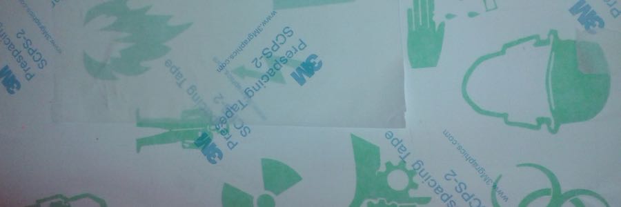
Cutting
I used the Roland CAMM GX-24 vinyl cutter at FabLabWgtn to cut out my design, I used Adobe Illustrator on the control machine to drive the cutter directly, fortunately the process of bringing and Inkscape SVG into Illustrator went more smoothly than the other way around (Hooray for Open Formats!). Finally I spent about 20 minutes carefully weeding the sheet to arrive at my final product: