3D Scanning
Equipment
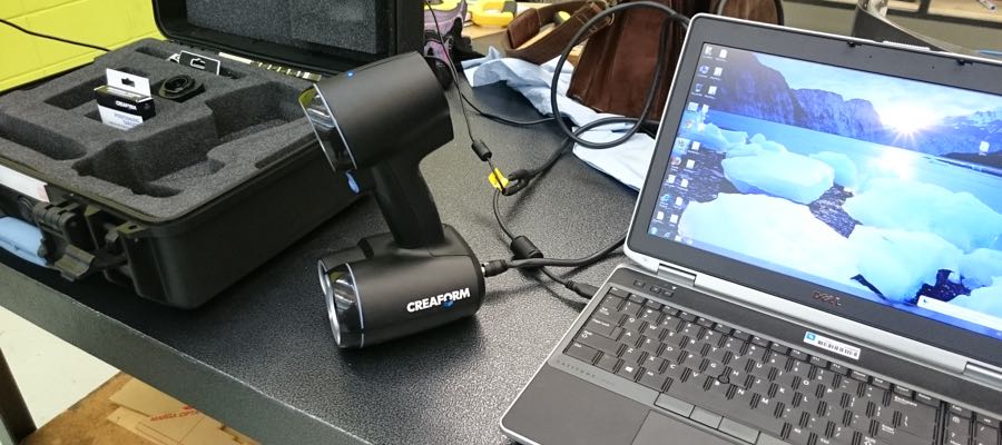
The 3D scanning equipment available in my lab is a Creaform GoScan structured light scanner. The GoScan is a proprietary scanner targeted at the industrial metrology world with a high resolution (0.5mm volumetric) over a large area (25m3+).
Subject Matter
The part I have chosen to scan is a Festo pneumatic regulator assembly, I chose this part as it is a geometrically complex part that would be difficult to draw manually (and I need a relatively accurate 3D model of it for another project).
Software
As the GoScan is a proprietary scanner, the software is similarly proprietary. The software comes in 2 components, the scanning host software (VXElements) and the mesh preparation and cleaning software (GoModel). For the purposes of this subject I will perform a basic scan using the host software and isolate the desired geometry using the mesh cleaning software.
The Process
Step 1: Preparing the object
The object to be scanned needs to be relatively matte in finish as a highly reflective surface will not allow the structured light pattern projected by the scanner to be easily 'seen' by the scanner. As this part is matte finished already we don't need to apply any surface treatment, in cases where this is necessary I have found that NAW dye-penetration developer makes an ideal 'de-glossifier'.
Step 2: Markers
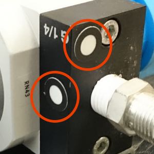
This is an optional step with the GoScan, but one worth doing. Part of the scanner kit are boxes of adhesive retroflective markers that provide a reference point for the scanner, the GoScan is capable of running without these operating purely on geometry tracking however they will prove very useful in a subsequent step. The markers can also be used to easily establish an orientation of the object in cartesian coordinate space.
Step 3: Configuring VXElements
Surface Detection Mode
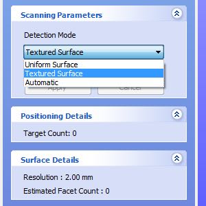
Before scanning the host software needs to be set up to work best with the specific properties of what is being scanned, the first of these settings is the detection mode. Uniform surface detection will assume a notionally perfect surface and is ideal for capturing smooth surfaces with minimal noise. Textured surface detection will include any surface imperfections in the final scan and thus is better for capturing realistic models with surface texture intact. For scanning the regulator I used the Textured Surface detection mode.
Scan Resolution
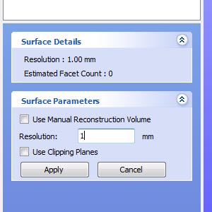
The second configuration element that needs to be configured before scanning is the surface resolution. This setting affects the resolution at which the preview image and final mesh are generated, critically for the GoScan this is not the resolution at which the scan is captured, the scanner will always capture as much data as it can making it possible to switch to a higher resolution after scanning (assuming enough data has been obtained). I find it best to perform the scan at a maximum of 1mm resolution to minimise the load on the computer during scanning and thus give better responsiveness.
Step 4: Starting the Scan
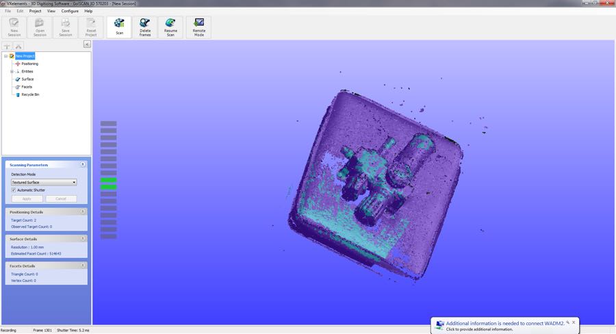
The next step is to perform the scan, the trick to getting a good scan with the GoScan is a very smooth and consistent movement with the scanner ensuring that it is always kept normal to the face of the object being scanned. The above image shows what is seen on the screen during a scan and provides important information to the operator.
Captured Data
A rough 3D model of the object being scanned is generated and shown during the scanning process, this is shown in purple.
Area in View
The area of the model shaded in teal is the area currently in the view of the scanner, this should be used to judge what moves are needed to acquire currently uncaptured areas of the shape and to help in keeping the scanner locked on to the geometry of the object.
Range Indicator
The bar graph on the side of the window gives an indication of how far from optimal the scanner currently is from the object being scanned, by keeping the number of shaded squares to a minimum the operator can ensure that the scanner is at the best possible distance from the target. There are also 3 indicator LEDs on the top of the scanner unit that communicate a simplified version of this.
Step 5: Scanning from Multiple Angles
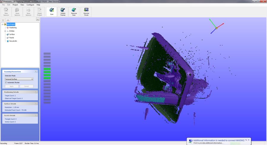
This is the point in the process that the retroflective markers applied earlier become mandatory, the markers provide an absolute reference point for the scanner even if the surrounding geometry has changed. In this case the part has been flipped over to facilitate scanning of the underside, as the surface the part is sitting on is being scanned along with the part itself this changes the apparent geometry.
Step 6: Cleaning
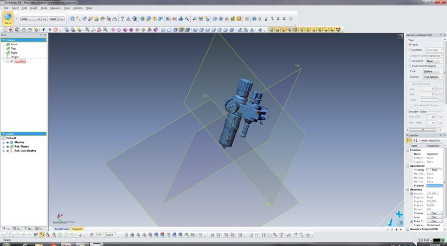
Cleanup of the mesh is done using GoModel and is relatively straightforward. During the import wizard the 'Find Edges' function allows us to delete the facets that are at the software detected interface points. This effectively separates the desired model from the surface on which we were scanning.
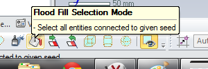
Once this has been done we can use the 'Flood Fill' selection tool to select all of the facets of the desired model (This functions much like the paint bucket tool in image editing software) and invert the selection to delete all undesired data.
3D Printing
As a project for 3D printing I wanted to look at making an object with a complex series of internal chambers as these would be extremely difficult to manufacture with traditional manufacturing technologies.
Design
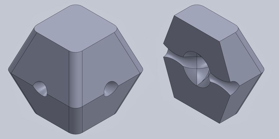
I designed my prototype part in Solidworks as this is the design package I have been working with since Week 2, the design of the part is intended only to demonstrate otherwise difficult or impossible elements that are made possible through 3D printing, I have a particular interest in this sort of structure as it has significant implications in the realm of pneumatics.
Printer
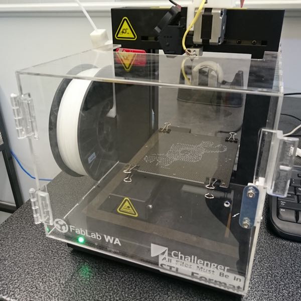
The printers we use in the lab for the bulk of our printing are the PP3DP UP Plus printers, these are low cost FDM based proprietary printers manufactured in China.
Modifications
You may notice from the photo that the UP Plus printer I used has been slightly modified by the addition of an acrylic enclosure manufactured on the FabLab lasercutter. The reason this was added was to keep the build environment at a stable, relatively hight temperature to alleviate the problem of warping.
Software
As the UP Plus is a proprietary printer we are restricted to using the UP software which acts both at the CAM/Slicing software and the host software for machine control.
Preheating
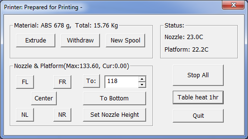
Before starting to configure the machine, the preheat process should be started to ensure that the build bed and environment are up to temperature by the time we want to start printing.
In the UP software this is done from the Maintenance window using the 'Table heat 1hr' button that, as its name suggests, will keep the bed heater on for 1 hour.
Print Settings
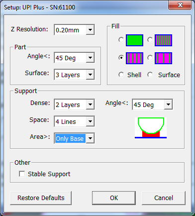
First up the print settings need to be configured for the object that we want to print.
Z Resolution
This setting governs the layer height, in the UP software we have options at 50µm increments between 150µm and 400µm. In practice layer heights above 250µm give very poor print quality on the UP so it's best to stick between 150µm and 250µm. For this object I am using a layer height of 200µm to give a balance between print quality and speed.
Fill
Objects printed using FDM are rarely printed as fully solid. The UP printer allows for 4 preset levels of infill density, in this case the object does not need to be particularly mechanically strong so the fill selected is the second lowest to save on polymer.
Angle<
This governs the angle at which solid support will be filled underneath a surface to prevent sagging of the surface layers into the gaps in the infill. 45 degrees works well.
Surface
This sets the number of solid layers to print on the outside of the object. For most prints I find that 3 layers gives a good surface finish but for objects where strength or surface integrity (for example being waterproof) is important the UP software allows up to 6 surface layers to be printed.
Support
Support material is essentially 'scaffolding' for a 3D printed object, it allows the printing of objects with overhangs that would otherwise be unprintable.
-
Dense & Space
Governs the way the support structure is built, these values are the default and seem to work very well. Every time I have experimented with these settings I have made things worse, birds-nest-in-the-printer worse.
-
Area
Very small overhangs can self support, this sets the threshold for the minimum area of overhang required before support is printed. The minimum option is 'Base Only' that will prevent any support material being printed that is not connected to the base of the object. I have selected the 'Base Only' option to prevent support material from being printed in the inaccessible internal cavities of my object.
-
Angle
Overhangs can self support if the angle is steep enough to allow the filament thickness to overlap with the layer below sufficiently. 45 degrees is the general 'rule of thumb' for self supporting overhangs however in practice angles as low as 30 degrees can be printed supportless with some degradation of surface finish.
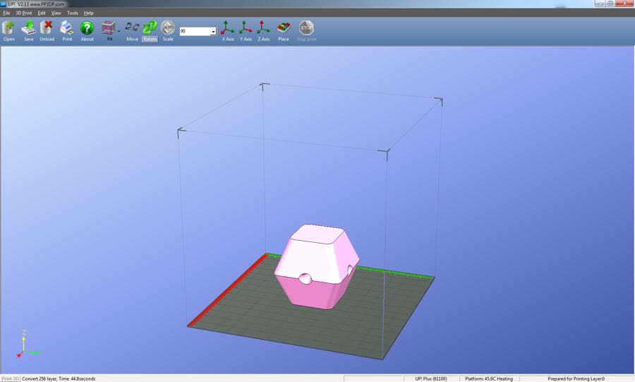
Preview
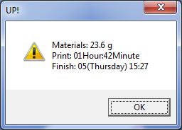
The UP software can give us an estimate of the amount of time and polymer required to manufacture the part with the current settings, I always tweak a few settings and attempt to reduce the print time where possible however I have run prints on these machines that have take 30+ hours without issue.
Printing!
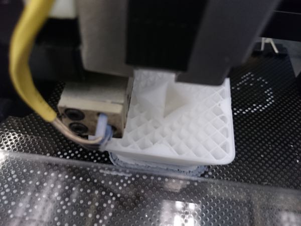
All that is left now is to run the print itself, after hitting the 'Print' button the CAM data is transferred to the printer control board and the print sequence is started.
The print can be seen underway in the image to the right, the internal structures inclusing the infill and the interior cavities are clearly visible. This part is being printed on perfboard to help with bed adhesion and with a raft to prevent the perfboard from compromising the bottom surface finish of the final object.
Finished
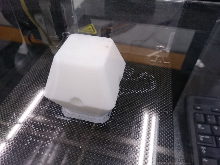
The part came out well and had only slight surface sagging on the internal overhangs that were printed without support. Something I would like to work on in future is a series of 3D printed pneumatic logic gates that take advantage of this ability to print arbitrarily complex internal structures.
Files
- Files for the 3D printed part are available to download as STL or Solidworks Part.
- The resulting STL from the 3D scan is available here (Compressed using LZMA as it's a chunky file).