
Assignment of this week is to design and build a wired &/or wireless network connecting at least two processors
Internet of Things (IoT) - the concept of the computer network of physical objects ("things"), equipped with built-in technologies to communicate with each other or with the environment, which considers the organization of such networks as a phenomenon that can rebuild the economic and social processes, are excluded from the of the actions and operations need human intervention.
In this case it will be interesting to do my robot blue-tooth driving
For communication with the Bluetooth module will use SoftwareSerial. This will give us an opportunity to connect Bluetooth module to virtually any microcontroller pins.
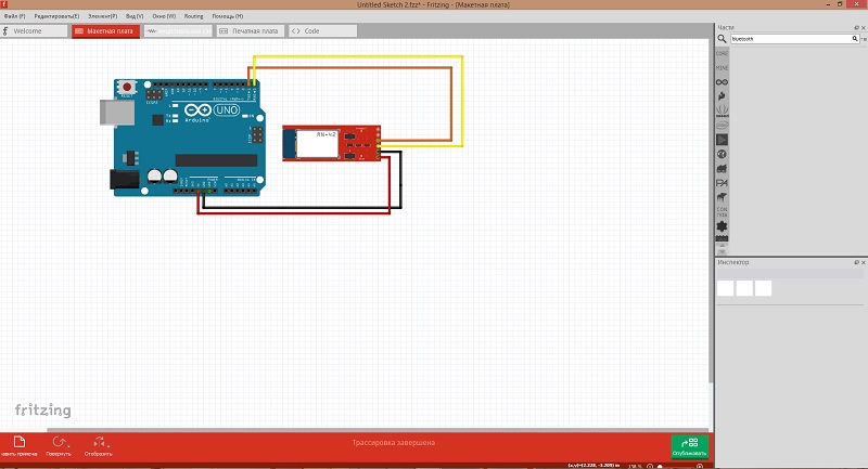
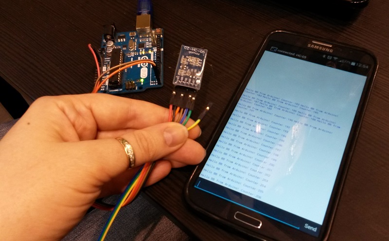
Now we need to physically connect a Bluetooth module to the board Arduino. Module HC-05 has the 4th contact (they were signed on the motherboard). Two of them - the power module. They connect to the standard power supply + 5V on the board Arduino. The other two - a bus UART interface: RX and TX, responsible for transmitting and receiving data. Contact RX must be connected to pin on the Arduino, which have a function TX, TX and pin to pin on the Arduino, having a function RX.
So contact RX Bluetooth module connect to pin 3 board Arduino, and the contact TX - 2 to pin boards.
Now you can fill in the source code to the microcontroller.
I use bluetooth HC-05, because It has the opportunity to fill in the Arduino sketch, without turning off the unit by RT-TX pins.
Specification bluetooth module HC-05:
Connecting the bluetooth module HC-05 to Arduino
VCC - +5v (+5 volt)
GND - GND (ground)
RX - TX (arduino pin)
TX - RX (arduino pin)
LED - (don't use)
KEY - (don't use)
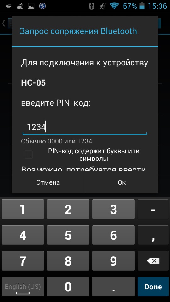
After connection you see the blinking of blue LED on the module with a frequency of about 4 times per second without pause, this display module enabled without any connections to any device. Now we turn to the settings of phones bluetooth (I use the phone FLY IQ446 with android 4.1.2)
For electronic design I use the program cold FRITZING. This program has user friendly interface and very useful at designing of breadboards.
Turn on bluetooth on your phone and search for new bluetooth device, find the device with the name of HC-05 and connected to it at the password prompt, enter PIN 1234
After a successful connection to the Arduino IDE go and write a simple sketch to send data to the arduino to your phone via bluetooth module.
int cnt = 0; // register
void setup() {
Serial.begin(9600); // port initialization
}
void loop() {
cnt++;
Serial.print("Hello BB from Arduino! Counter:"); // output of inscription
Serial.println(cnt); // derive the value of the counter on new line
delay(1000); // wait one second
}
Loading sketch into Arduino and then go to the phone and install the program to display data received via bluetooth. Download the app from Google Play application Bluetooth Terminal and install on your phone.
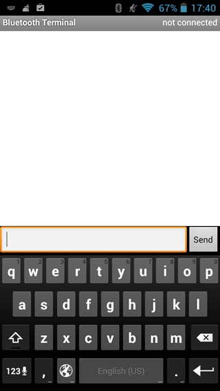
There will appear the window during starting the application^
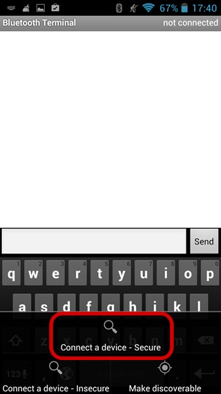
Open the settings menu and select Connect a device – Secure (it marked red in the picture)
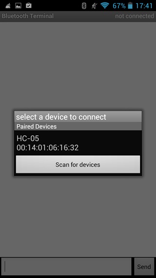
Choose our bluetooth module HC-05.
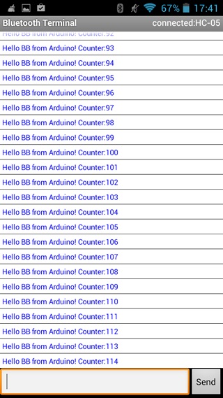
A window appears displaying the data that we arduino sends phone.
In my task I use two microcontroller boards: Arduino and my circuit board with Attiny.
For programming Attiny 2313A-SU I use Arduino ISP.
Here is code:
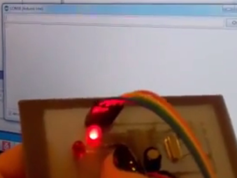
Here is video
When I press button LED ups and send to port "1".
Archive with program is here.