Output devices is user-computer communication devices and devices used for communication between computers, devices and other peripherals, which may be used for input/output purposes, like network interface cards, modems, wireless networking devices, as well as mechanical output devices, like solenoids, motors and other electromechanical devices.
Assignment of this week is to add an output device to a microcontroller board you've designed and program it to do something
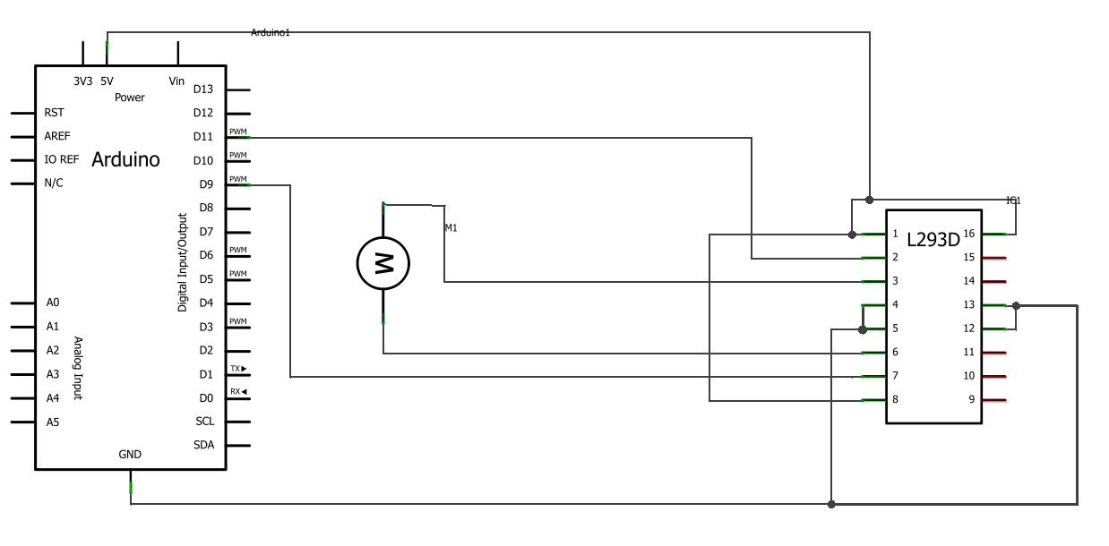
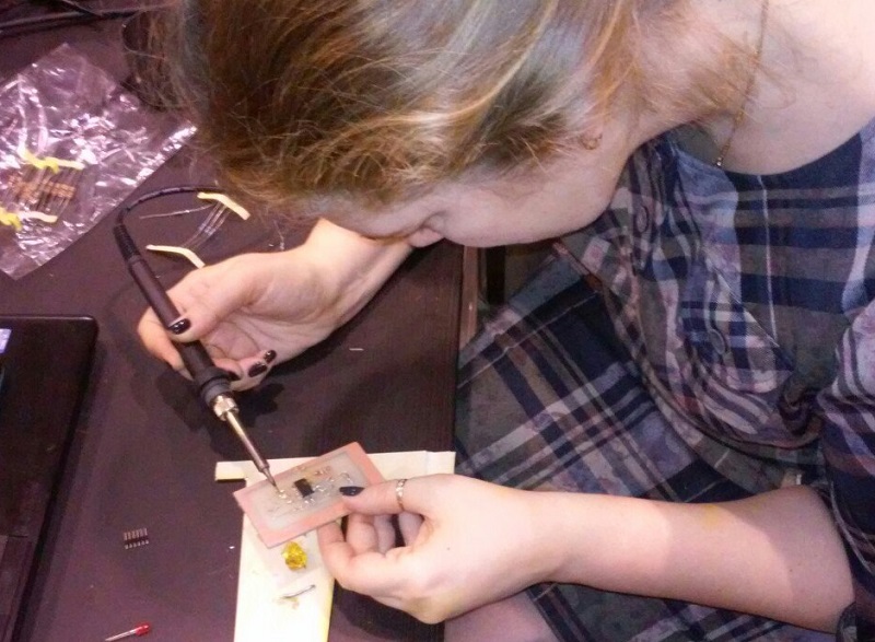
In my project output devise is two DC motors.
The outputs of the microcontroller provides a maximum current of 40mA. I use L298N driver is a dual engine, which allows you to control stepper motors and DC motors. L298N can control two motors with a maximum load current of up to 2 A per engine. You can enable the parallel connection of a driver to operate a motor providing a maximum load of up to 4 amps.
The chip is designed to control two DC motors.
Briefly on the findings of the chip:
GND - common wire, also known as "ground".
Vss - the power circuit (5V to the Arduino board)
Vs - powered engines.
It is recommended to use a separate power supply for the motors, but this conclusion can also be connected to the Arduino 5V conclusion. ENABLE - on and off the channel, in this case, they always served a logical unit (high voltage) can be connected to the same place and Vs. INPUT - control the corresponding output OUTPUT, a high level at the input connects the output to the supply voltage and the low - to the ground. Thus, by attaching a motor to two conclusions chips, we can rotate it in two directions.
Well, the circuit is ready and you can write a sketch. In addition to the sketch of the engine management includes working with EEPROM (non-volatile rewritable memory), as well as the work of a serial port (an indication of the direction of rotation, increase and decrease speed).
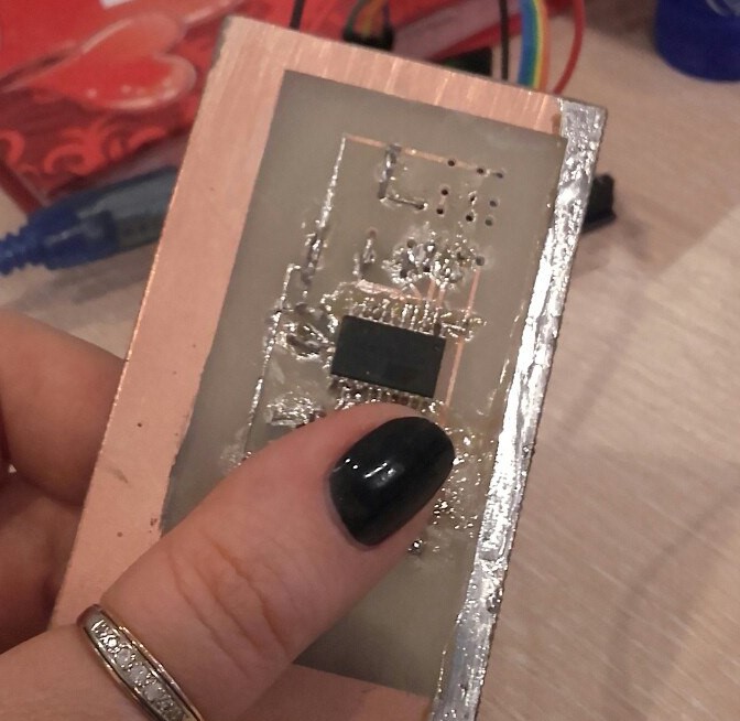
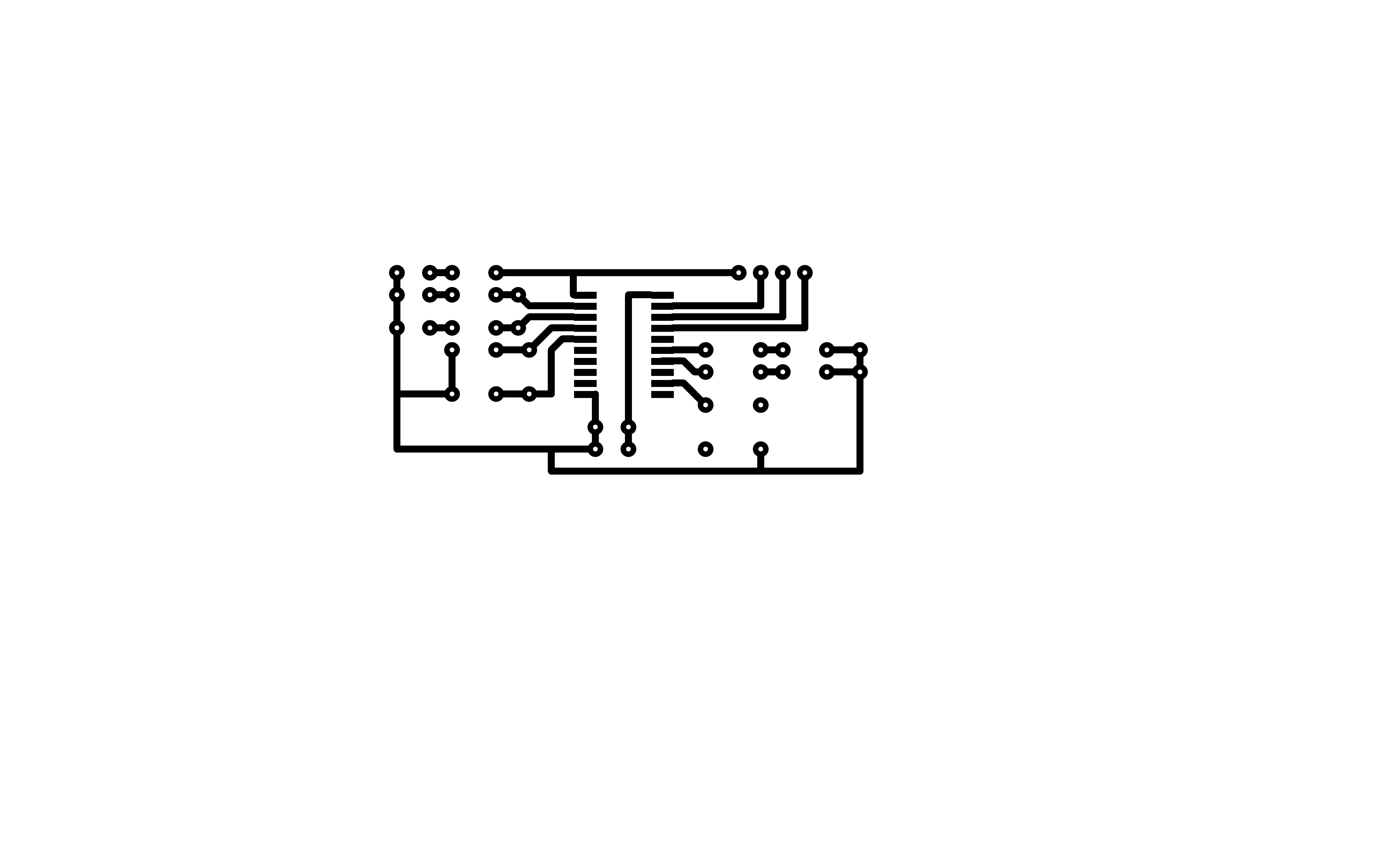
I have done circuit board on Epilog Legend Mini 24 Laser
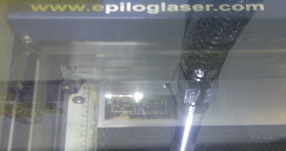
using Sprint-Layout 6.0 (".lay6")
For laser cutter I save the file as (".bmp")
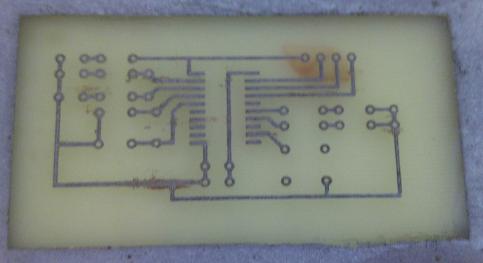
PCB sheet was treated by sandpaper. Then the PCB covered with one layer of acrylic paint. Paint covers to track remained after etching. After laser cutting dropped into a solution of ferric chloride and water (1:2). After 5 minutes, the board is ready. Washed it with water. Removed the excess paint with acetone. Drill a hole in the ground fixing components.
Here is video
The output is the when you press on the button second LED ups and send to port "1".