Input devices - a hardware or peripheral device used to send data to a computer. An input device allows users to communicate and feed instructions and data to computers for processing, display, storage and/or transmission.
Assignment of this week is measure something: add a sensor to a microcontroller board that you've designed and read it
I will use digital camera in my final project. At the first prototype I will use Raspberry Pi for recognising faces.
We need some photos of the object in a real environment. The sample will be more similar to what we recognize then better will be results.
The next step is to create two folders - for positive and negative examples.
After that we take some photos and use the soft OpenCV to create a new sample from the existing 2-3 images.
Now we have two folders - good.dat and bad.dat
Bad files look like:
Bad\1.bmp
Bad\2.bmp
Bad\n.bmp
Training takes place in two stages. The first stage - all the positive images are provided to a common format. This should be located in a folder OpenCV program. Take the one that corresponds to your system. I have it "opencv \ build \ x64 \ vc10 \ bin". The program is called opencv_createsamples.exe.
Create the final stage
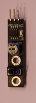
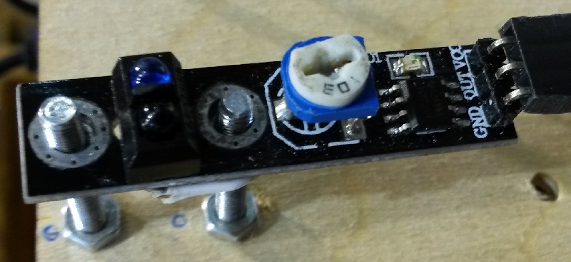
Also in my final project I use line sensors as input device.
Line sensors check if the surface is black or white and sends data to controller. In my project there are two line sensors. So if the line on table intersects with sensor it recognize it. If right sensor got the signal we rotate left wheel faster.
This week I try to describe the process of creating a robot which drives along the line. This task is a classic, simple ideological, it can be solved many times, and each time you will discover something new. The solution to this problem and the implementation of the solution allows to acquire the necessary basic skills for further improvement in robotics.
There are many approaches to the task of following through. The choice of one of them depends on the particular design of the robot, the number of sensors and their location relative to the wheels, and each other.
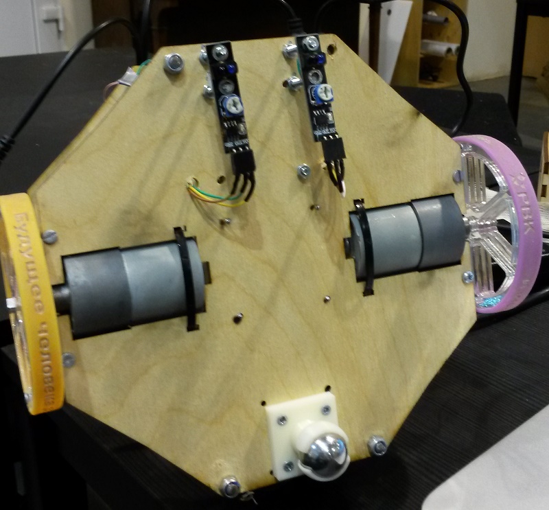
My robot has a platform with two wheels and two line sensors disposed on the bottom front of the wheels of the robot.
What I use:
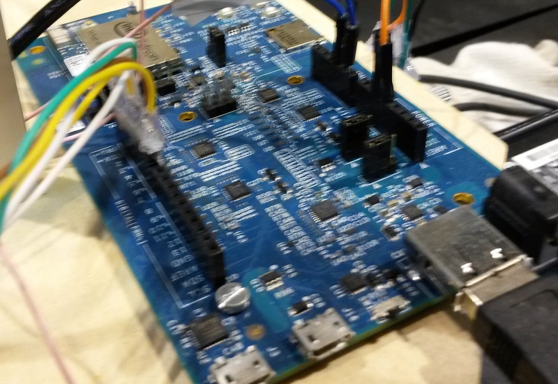
Galileo Edison
Two-wheeled platform. On the bottom part of the platform you can see balancing ball, which is designed to hold the balance of the platform.
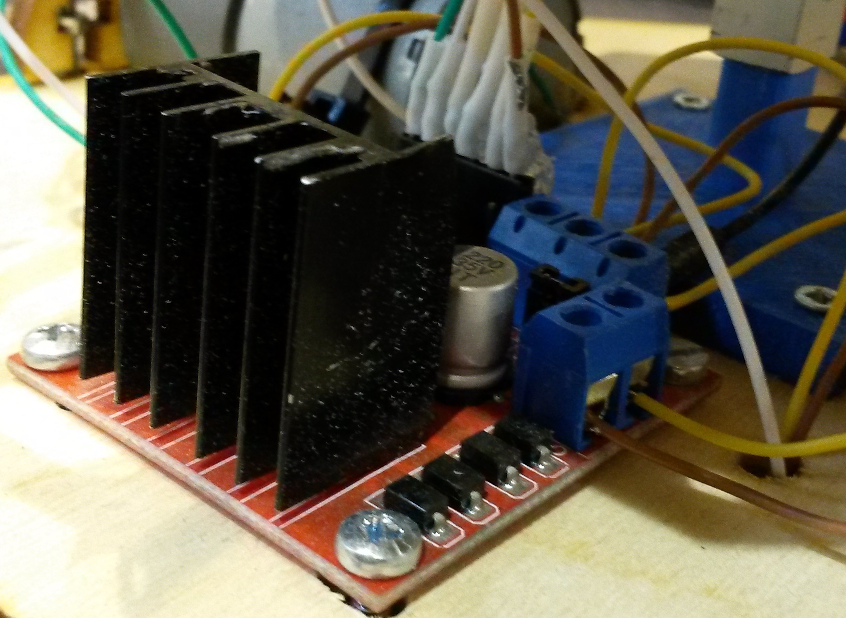
Motor Shield
Two line sensors
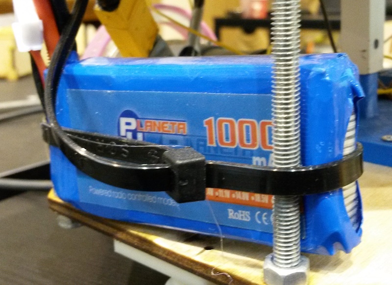
Lipo battary
Lipo battery is preferable, because they have a high current return.
When you gather all parts into robot we can start with programming.
Program have to make our robot to move along the drawn line. In the project we will use a white line printed on black surface. This my choice because we have black tables in our fablab.
The basic idea of the algorithm is that the line sensors give a logic "0" when "see" white and "0" when "see" black.
On the line the robot must pass the track between the sensors, that is, both the sensor must demonstrate "1".
When you turn to the right path, the right zooms in on the sensor track and starting to show a logical "0". When turning left, the left sensor shows "0".
Thus, we obtain a simple system with three states:
You can see the red light turns when the line sensor catches the white line and after that the opposite wheel begins to spin faster to return the robot to the way.
Week 11.Input devices. Addition
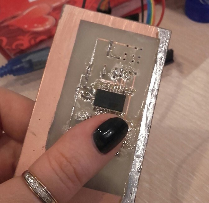
I have done circuit board on Epilog Legend Mini 24 Laser using Sprint-Layout 6.0.
For programming I use Attiny 2313А-SU.
#include #include #include #define output(directions,pin) (directions |= pin) // set port direction for output
#define input(directions,pin) (directions &= (~pin)) // set port direction for input
#define set(port,pin) (port |= pin) // set port pin
#define clear(port,pin) (port &= (~pin)) // clear port pin
#define pin_test(pins,pin) (pins & pin) // test for port pin
#define bit_test(byte,bit) (byte & (1 « bit)) // test for bit set
#define bit_delay_time 102 // bit delay for 9600 with overhead
#define bit_delay() _delay_us(bit_delay_time) // RS232 bit delay
#define half_bit_delay() _delay_us(bit_delay_time/2) // RS232 half bit delay
#define input_port PORTB
#define input_direction DDRB
#define input_pin (1 « PB4)
#define input_pins PINB
#define serial_port PORTB
#define serial_direction DDRB
#define serial_pin_out (1 « PB2)
void put_char(volatile unsigned char *port, unsigned char pin, char txchar) {
//
// send character in txchar on port pin
// assumes line driver (inverts bits)
//
// start bit
//
clear(*port,pin);
bit_delay();
//
// unrolled loop to write data bits
//
if bit_test(txchar,0)
set(*port,pin);
else
clear(*port,pin);
bit_delay();
if bit_test(txchar,1)
set(*port,pin);
else
clear(*port,pin);
bit_delay();
if bit_test(txchar,2)
set(*port,pin);
else
clear(*port,pin);
bit_delay();
if bit_test(txchar,3)
set(*port,pin);
else
clear(*port,pin);
bit_delay();
if bit_test(txchar,4)
set(*port,pin);
else
clear(*port,pin);
bit_delay();
if bit_test(txchar,5)
set(*port,pin);
else
clear(*port,pin);
bit_delay();
if bit_test(txchar,6)
set(*port,pin);
else
clear(*port,pin);
bit_delay();
if bit_test(txchar,7)
set(*port,pin);
else
clear(*port,pin);
bit_delay();
//
// stop bit
//
set(*port,pin);
bit_delay();
//
// char delay
//
bit_delay();
}
int main(void)
{
/* Replace with your application code */
DDRB |= 1«3;
bool down = 0;
while (1)
{
if(PINB & 1«3 > 0 && !down){
down = true;
put_char('1');
}else if(PINB & 1«3 == 0){
down = false;
}
ORTB|= 1«4;
PORTB|= down«5;
_delay_ms(500);
PORTB|= 0«4;
PORTB|= 0«4;
_delay_ms(500);
}
}