
Our assignment for this week was:
We decided to make a solar panel orientation system because it is really interesting task and seems to be quite simply implemented (or seemed...). It has to be controlled either on feedback from light sensors (tracking the sun), or manually (from the computer).
Here's the concept (or to be more correct, the current version) of our machine. What's good about that - it is universal (with adding some changes it can be turned into a turrel for example. I guess that it would be interesting to make
Our presentation materials describe the basic concepts. You can find them here, but I woluld like to give you a short intro to this subject here as well!
Designing the machine (I think of it as if it was a robot) includes:
mechanics: parts design, transmissions.
We designed the whole mechanical parts from the scratch (because we didn't get the kit due to the custom issues) and that was really fascinating! We had a legal copy of GearGenerator on one PC in our lab and we started experimenting with it.
electronics and elecrics: sensors, power electronics and motors, interfaces (their physical implementation), user interface (if any), power supply.
For now we've had some parts working on arduino-like board, but that's not the desirable limit for our efforts. The whole thing has to be modular with simple nods (like separate sensor-drivers or motor-drivers) connected with specific interface. Making so would allow us to scale this project in fiture and also has to ease the debugging process and ease the parallel development. We are using 12V DC adapter with 1A maximal output current for now.
programming: low-level programming (for motor-drivers, interfacing to connect to PC) and high-level programming (GUI, if any).
At the moment we only have motor-drivers to control and the main program (interfacing the motor-drivers and interviewing the sensors). Also our system is in fact an automated tracking system, so user doesn't need any control (excepting the critical situations) on it. Thus our user interface only has to provide user with statistics on the machine work (like solar radiaton intensity or sensor-reports)
other directions (like math if we are trying to make our own g-code interpretation or maybe some physics for wxplaining the process this machine is processing).
This is part is being developed right now. Basicaly it may include research on solar panel and the power calculation to find out at what conditions do we gain any profit or economy from this machine. Or some automatic-control algorythms (mathematical parts) that would allow us to minimise the power consumtion or to reach optimum at any other parameters.
This approach gives an opportunity to divide the work on our projects on doffernt parts and make it more efficient by dividing everything on simple tasks.
My personal contribution at this moment is (mainly) designing all the mechanical parts for upper degree of our machine in Corel Draw and fabriceting them on the laser-cutter (mechanical design), some parts of systematisation of the process and rationale (Project developement). ALso some parts of power-electonics (research on the possibility of using L298 for our unipolar stepping motor) and fabkit fabrication.
As a team we made some improvements into machanics and managed to split our wirk into different workflows (that was kinda cool).
Later I would like to contribute with working on sensors, on hardware and software interfacing and also on design-issues for the GUI.
First thing was to shape the details from basic graphical prinitives and get the match in different details sizes:

Then I smoothed the shapes using polylines:

Then the time came to play with GearGenerator:

There was no task to make really well calculated transmission with a certain gear ratio, just to make something that fits the basic design conception (though I know from machine design course we had in MPEI that this approach has quite limited application area and if we want to make it serious we will need the strength researches and other complications). After generating the transmission we exported it as the vector-design and imported it in CorelDraw:

|

|
After import we can make sure that all the holes are placed where they need to be placed and the whole machine will work! And the gears - we can cut them from plexiglas (you ay use the acrylic plastic, but we had plexiglass only, so...). One has to have a hole (play with sizes to make sure it will get on the shaft tight) and the other (bigger one) has three holes to be screwed to the vertical rack.
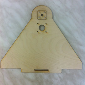
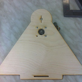
That what we have when some of those parts are laser-cutted and partially assembled:
|
|

|
The construction we had in the result wasn't rigid enough (because we were using 3mm-plywood and the parts are relatively big), so we had to strengthen it with aluminum structure. We also had some problems with assembling the transmision for tle lower degree, because we wanted to use a toy-truck for a toy-tank instead of the usial belts and also because of the balance (the stepping motor was a little too heavy for the whole structure and was draging it away from the operating positions. There are some ideas about how to solve those problems, and we shall try it shortly!