Homework assignment
Make something big.
Design
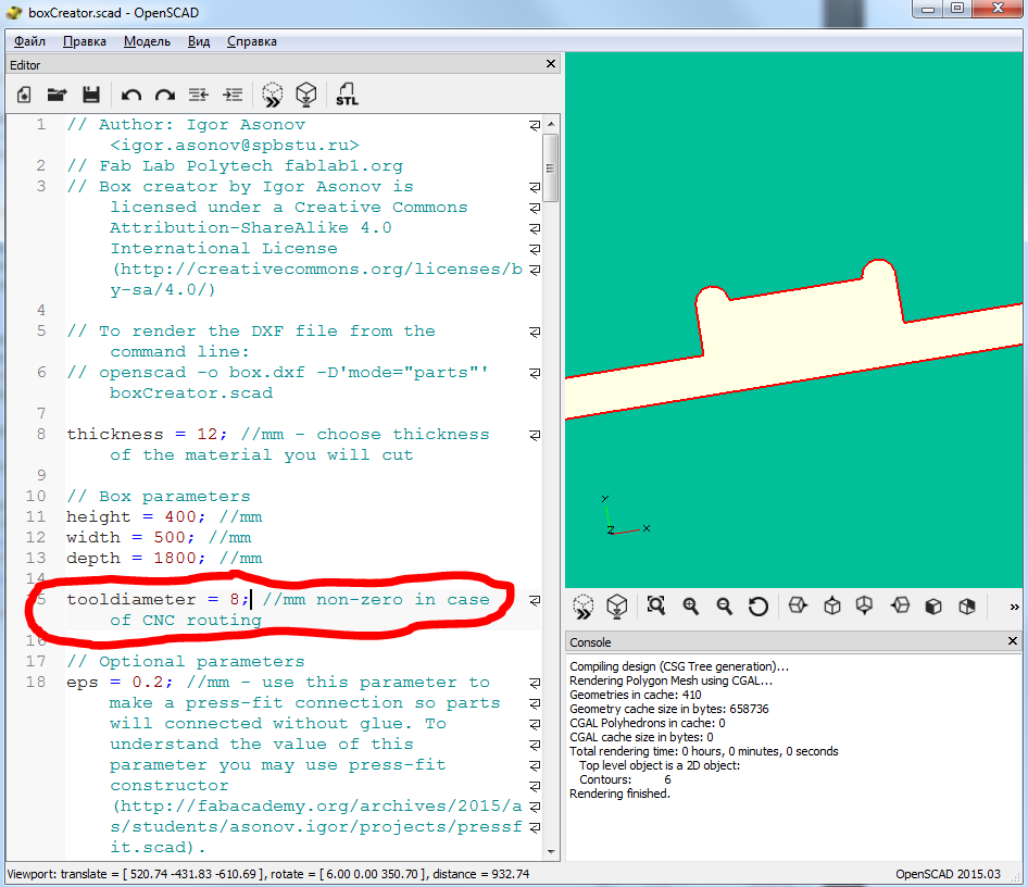
I decided to devide designing process into two parts: basic in OpenSCAD and final in SolidWorks, because it's easier to check the design by making an assembly. So I used OpenSCAD and changed my box creator to be used not only with laser cutters but with CNC router also. New parameter is "tooldiameter" - if it's non-zero there will be special openings for CNC router manufacturing:
There are several modes inside the program:
- "full" - drawing of the whole box with 6 sides;
- "full-1" - drawing of the box with 5 sides - you can put anything inside the box;
- "half" - export only half of the box;
- "door" - drawing of the box with door;
- "3dview" - preview of half of the assembly.
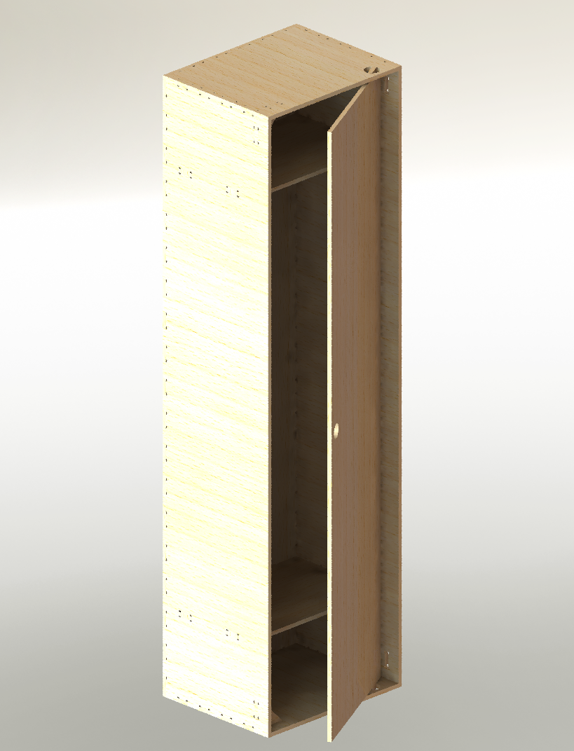
I created design using "door" mode and export it to dxf-files. These files were imported in SolidWorks 2013 where I made parts using imported sketches, designed two new parts (partitions and corners) and added cuts for them, then made an assemly:
Make
I used ArtCAM to generate g-codes from dxf-file (exported drawing from SolidWorks). If there are holes and cuts inside your parts - they should be processed first. Choose them in ArtCAM, go to Processing tab (at the left bottom corner) and press "Profiling" (looks like "T"):
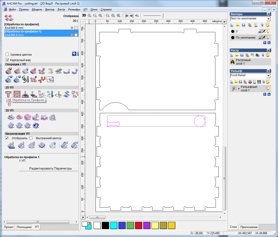 Choose "Inside" and go trought wizard (it will ask you the depth of cutting, tool parameters) and press "Calculate now". After the g-code generation you can save it using menu "G-code->Save g-code..". After you cut internal things on you part - made the same with outside profile of your part.
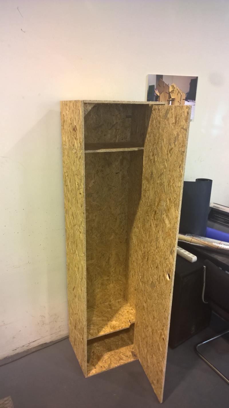 Parts of the system connected with each other using friction.
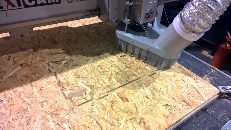
I used 8 mm tool, 1500 mm/min working feedrate and 15000 rpm for spindle. Material was 1.2*2.4 m OSB wood.
Source files (dxf, SolidWorks 2013): zip-archive.