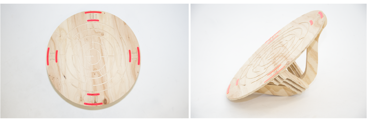
WEEK 8 | Computer-controlled Machining

Cardboard modeling
I used the laser cutter and a 4.3mm thickness cardboard to test the design.
TEST 1:
I scaled my Illustrator file in order to have 3.9mm wide joins.
What I wanted to improve:
- the proportions: I needed to reduce the diameter of the disc;
- the joins.
TEST 2:
I set the z-axis in the middle of the board to cut my joints in a corner. The laser didn't cut all the way through because of the board's convexity. So I turned it upside down and I put some tape on the corners before printing the all file. Also I didn't want to waste to much material so I just cut 2 legs and the top of the table.
I was quite satisfied with the result so I moved on to the ShopBot.
ShopBot Workflow - How to set up your files on Partworks
You can also use Inskape or a 3D software such as Rhino
2. Export your file as an '.dwg'
3. Open this '.dwg' file on Partworks
4. On Partwork's left window, set up the size and the thickness of your sheet: for us it was 2400x1200x12mm plywood
5. Then deselect "Use the origin offset" and close this window
6. Use the "Move, Scale, Rotate" arrow to position your objects as you want to cut them
7. Select the "Create Fillets" tool and add "Dogbones" tour your joins
You can also select "T-bones", it's an esthetic choice
Warning: you can use this tool only on PERFECT 90° angles. If you have to modify your angles, do it on Illustrator and come back to Partworks.
8. Use "Open Lines" tool to check if all your lines are closed. You have to click on each object.
Two points closer than the tolerance chosen will be joined.
Tip: lines of screws are not as strong as triangles.
Each layer contains the part that you'll cut the same way, with the same endmill, with the same depth and at the same time.
You can: cut all the way through with "Profile Toolpath", carve with "Pocket Toolpath" or drill with "Drill Toolpath".
You can also use different endmills to change the size and the type (down and up) of your cuts.
When you make the layers, always start with the "Screw" layer. Select all the "screw circles", right click on it and select "Move to: Screw layer".
Go to the layer that you need to focus on. The other layers should be locked. Select the objects. Select the "Toolpath" tab on the RIGHT side of your window. Select the type of Toolpath that you want to make: "Profile", "Pocket" or "Drill".
Screws' Toolpath:
Create "Drilling Toolpath"
- Cut depth: 2.0mm, it doesn't really matter for this Toolpath
- Select Endmill: it depends on the endmill you're going to use right after this cut
- NAME IT in a relevant way.
Profile Toolpath example:
- Start depth: 0 & Cut depth: 12.7mm
- 6mm endmill
- Number of passes: 4
- Create tabs
- Name it in a relevant way.
Start with the down mill toolpath :
Start depth: 0 | Cut depth: 3.5mm | Endmill: 6mm | Number of passes: 1 | ø Tabs.
Up mill toolpath :
Start depth: 3.5mm | Cut depth: 9.2mm | Endmill: 6mm | Number of passes: 3 | Add tabs.
12. Once you've finished setting up all your paths, select all of them and check the "Estimated Machining Time"
13. Save your Toolpaths in the same folder.
ShopBot Workflow - How to set up the machine
2. Change the bit if needed.
3. Set up the x-axis and the y-axis: "Cut(s)" --> "C3- Move X Y Axis"
4. Set up the z-axis:
- Open the "yellow window" and use the keyboard to move the mill where you want to cut,
- Use the aluminium plate to check it's sensing "bit",
- "Cut(s)" --> "C2- Zero Z Axis" : don't forget to HOLD THE BAND and wait for the software to confirm that its job is done.
6. Switch the aeration on
7. Insert the key
9. Click on "Cut part" and select the toolpath that you want to cut
10. Press start!
After the "Drill Toolpaths", take off the key and close the "yellow window" in order to safely screw your wood sheet.
On the left side: down bit,
On the right side: up bit.
ShopBot - Joins tests with Jasmin & Ben
At the begining, I just tried to replicate the join that I wanted to use. I quickly realised it won't work with a 3mm bit (left screenshot). So Wendy helped me to redesign it (right screenshot).
However, I was not satisfied by the aesthetic so I decided to use a simple press fit, add screws to the table and hide the screws with acrylic pieces.
The press-fit slots were too tight
Test 2:
all the joins were working and we decided to make 12.5mm wide slots for our press-fit joins.
Mill, sand & press-fit
Click here to download the Illustrator file.