Babeduino
List of components:
- ATMega328P
- 16MHz resonator
- 2x3 pin header
- 5V regulator
- FTDI header
- 1 green LED
- 6mm RST tactile switch
- 1 slide switch
Specifications:
- Options to provide power either with an FTDI cable or a battery
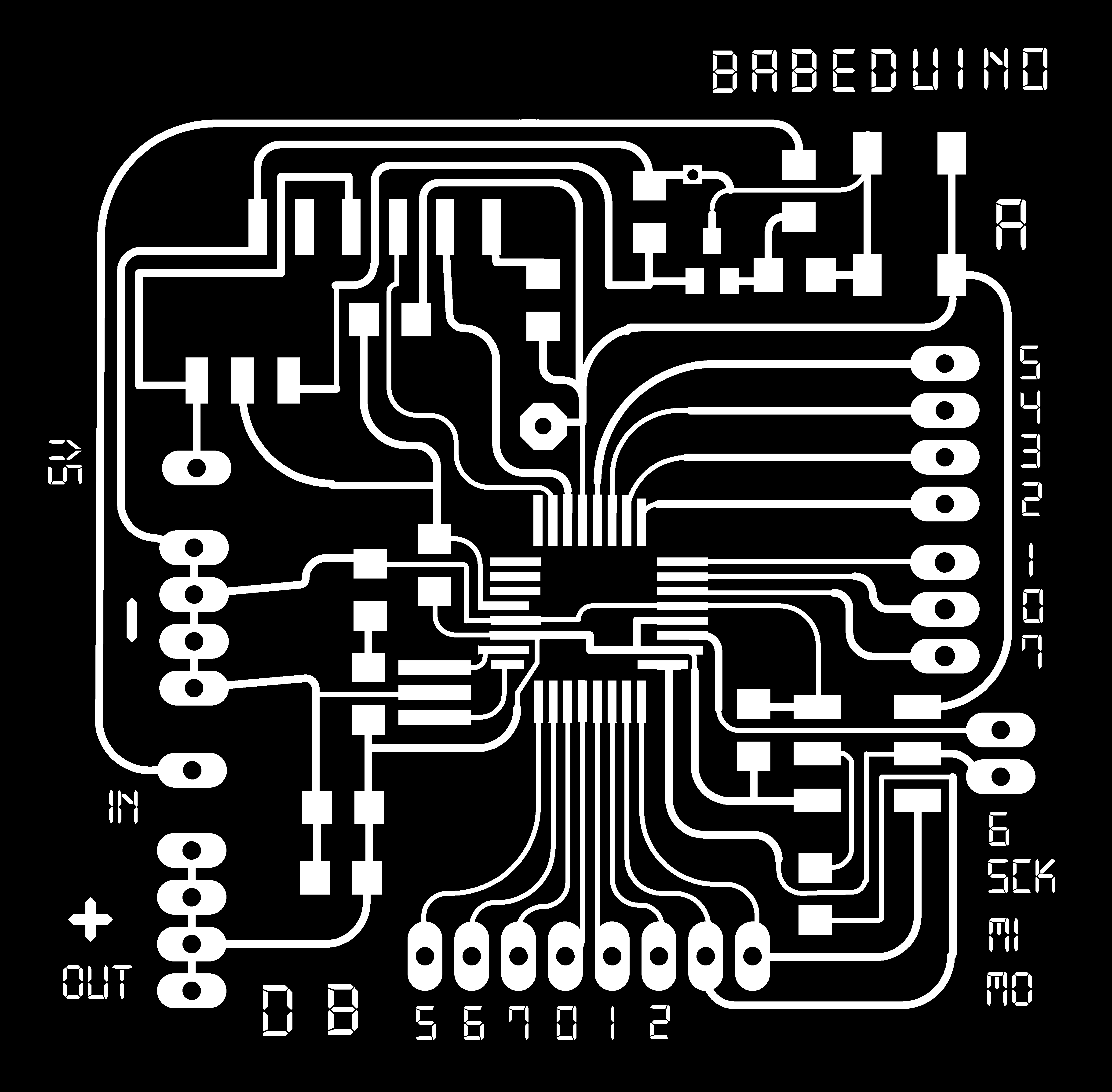
- 17 pin-outs: A0-A7 | B0-B2 | D5-D7 | MISO | MOSI | RST | SCK
- 1 "5V VCC" pin-out from the FTDI header which is not connected to the regulator
- 1 "VCC IN" pin: to provide power through a battery
- 4 "VCC OUT" pin-outs
- 4 GND pin-outs
My contribution:
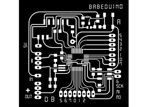
- Babeduino_1.0 schematic on Eagle
- Milling & soldering Babeduino_1.0
- Burning the bootloader and testing Babeduino_1.0 & Babeduino_3.1
- Pin and board naming on Photoshop
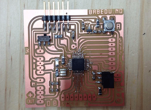
Babeduino_1.0
Even after having fixed the board, we couldn't provide power with the FTDI. Indeed, the "FTDI power" was connected to the other side of the regulator. We decided to use a battery.
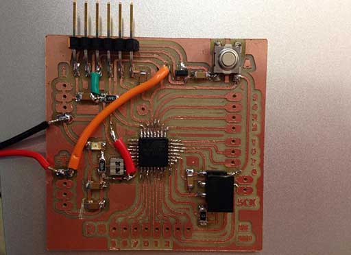
Programming:
We used a LED and a breadboard. We also checked the ATMega328 pinout board to make our Arduino program. We succeeded in making the LED blink! You can check the video on Jasmin's blog.
We were ready to make the final version of our Babeduino.
Babeduino_3.1