
MTM 2D Foam Cutter
Our group project allows the user to DRAW what to cut on a computer before sending it to the MTM to create using styrofoam.
Construction
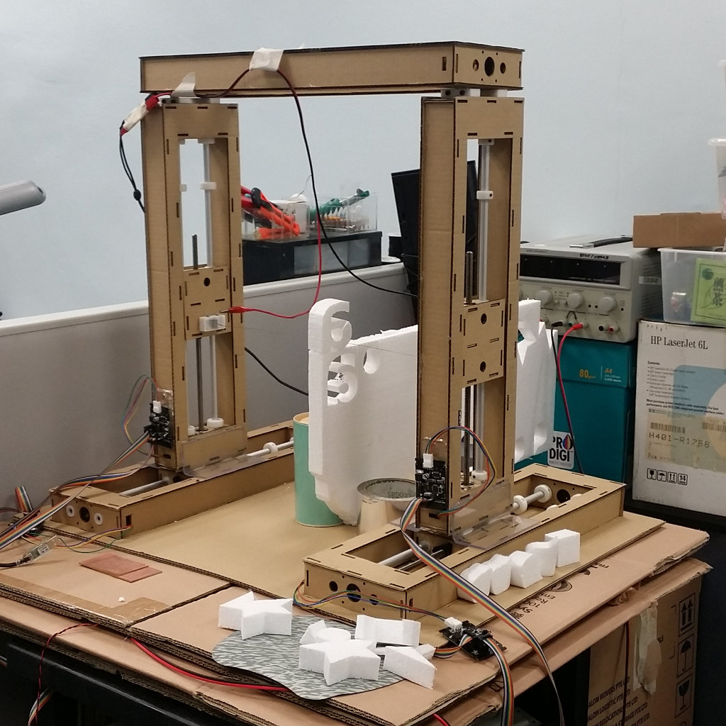
Our materials for the MTM system arrived and we were thrilled. Roy and Edward took it upon themselves to create the cardboard structures (without instructions) just by visually looking at the images on the MTM site. This resulted int the current structures which you see in the above image. However, in order to make the structure more stable, we added a top piece and plastic supports at the base. The base too had cut-outs to hold the horizontal struts to prevent them from moving. Roy and Edward, also 3D printed the extra collars and holders for the nichrome wire which was to be our cutter.
On simple manual testing the structure proved to be stable and could withstand the movements of the motor on all four sections. The plastic base supports also allowed us to mark the starting points where we could move the motors to begin our cutting process.
The learning points from this project is that using of cardboard allows great flexiblity and rapid turn around for concept generation before moving on to more rigid Engineering materials like Aluminium. The design that we had was simpler, but less rigid compared to the one given in the mtm site. This is because of the additional folds and overlaps plus glue adds to rigidity. Highly recommend the next team to build that the next time round. The plans can be found at http://mtm.cba.mit.edu/machines/science/
The plans for the cardboard cut-outs can be found here: MTM Cardboard Plans
Software Control
We first looked at the example programs from the MTM repositories as well as the gestalt repositories and the code provbided by Nadya Peek (PyGestalt). In particular, we looked at the example for the xy-plotter in the examples/machines/htmaa section.
By experimenting with the code in the examples, we discovered that the important functions/modules that we required were:
- initInterfaces()
initialises the FTDI-485 interface, in which we had to insert our own reference to the FTDI-485 usb interface we used (/dev/tty.usbserial-FTXW6Q4L) - initControllers()
which defined the controllers that we were using. In addition to the x-y plane, we had to include a u-v plane to handle the other side of the cutter. - initCoordinates()
in which were specified the coordinate system in "mm" units. To this we also inserted the measurements for the u-v axis - stages.move()
which sent the absolution move positioning to the node - stages.jog()
which moved the motors a predefined distance for positioning - stages.[x|y|u|v]AxisNode.spinStatusRequest()
which returned the status of the node after a move command has been sent to it - stages.xyuvNode.disableMotorsRequest()
which disabled the motors at the nodes to conserver energy.
We also discovered that the moves that the MTM made were in absolute units, which
were sent in a list to the method moves(). Hence, we could use the broad framework to
then create a 2D foam cutter:
BEGIN
    Create Machine with 4 Nodes (x,y,u.v)
    Initialise Nodes
    Manual position to (0,0,0,0)
    Read in .csv file
    for element in moves-List do
        move to element
    Disable motors
END
Using a heated wire between the vertical posts would cut the styrofoam when the plotting was complete. The only things to do were to decide where the cut would start and how to create the cut-path to be stored in the CSV file.
Image Creation
In order to create the cut-path, we looked at several ways of developing a workable solution, these included writing one using Tkinter or PyGame but found it tedious, as we are not Python-enabled. The next best solution is to use a vector-graphics system (InkScape) to draw the image and to try to obtain the cut-path from the generated file. Inkscape saves its files in .SVG (Scalable Vector Graphics) and has an XML format in text which can easily be parsed using python.
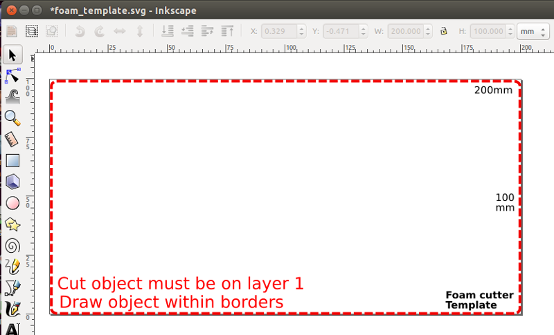
After several experiments, Rodney created a SVG template which could be used to 'draw' the image to be cut which would be parsed to obtain the cut-path coordinates. The SVG template should be used to create the image to be cut and should have only a single cut path. Objects are limited to Rectangle, Circle or Path. The template also provides a guide to how large the object is going to look like when cut. The cut-path should be transfered to layer 1 to be converted into csv using our program svg2csv.py. The output file, will have the samefilename as the .svg file but using the extension .csv.
As an example, the letter 'a' is drawn as text and the path traced out and placed on Layer 1. Changes to the path are made to allow for the cut for the internal body within the letter 'a'. There is no need to place the path at the top or bottom left corner as the program will take into account the cutting paths. As a check, we can see the XML code on the right showing the path on layer1.
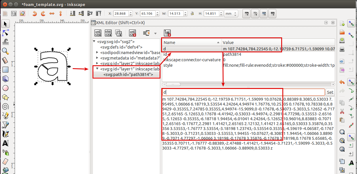
The SVG definition for the cut-path starts with the attribute 'd' and points a list of coordinates. A breakdown of this data is
- 'd=' indicates a path of coordinates, starting with
- m x,y which indicates the absolute coordinates of the first point
- x,y ... and the relative coordinates of the next points relative to the first point
- z is the terminating character.
The svg2csv.py program locates and reads in this string, extracts the necessary absolute and relative points and coverts them into absolute coordinates.It then identifies the leftmost point and uses that as the start cut point. The rest of the points are rearranged without changing their sequenece to form the cut. We will assume that cutting wire is positioned to (0,0) hence the first cut will be to the leftmost point, which will also be the last point of the closed figure. These are then transformed and saved as a csv file for cutting
An overview of the svg2csv.py program is:
BEGIN
    Search for the element tag "p" at layer1, discard all other information
    Identify either 'rect', 'circle' or path 'p'
    Extract absolute point and all relative points
    Convert path to absolute coordinates
    Determine leftmost point (start), sort rest of the points accordingly
    Add exit point to (0,0)
    Save as CSV file
END
SVG to CSV path converter (Python)
Video showing part of the foam cutting process
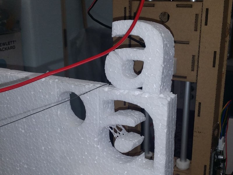
Result of the foam cut
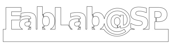
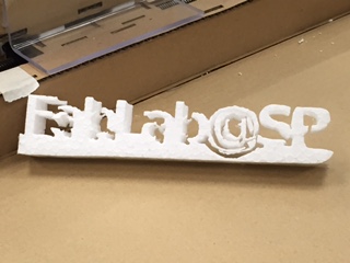
A more ambitious design: FabLab@SP
Result of the foam cut