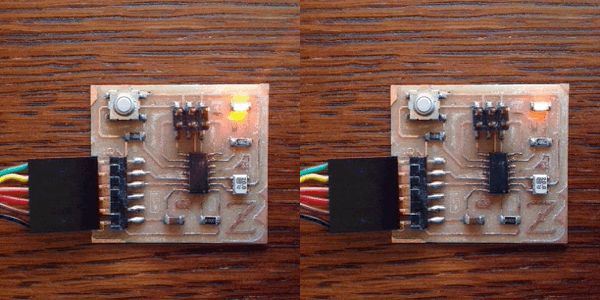
The assignment for this week is to read a microcontroller data sheet and program our board to do something, with as many different programming languages and programming environments as possible. Our "board" refers to the hello.ftdi.44.echo circuit board that we created two weeks ago as part of the electronics design assignment. The original hello.ftdi.44.echo circuit board has an ATtiny44a and a FTDI USB to serial interface. I modified the design to make a circuit board with these features plus a pushbutton input and an LED output. When I made the board two weeks ago, I tested the FTDI interface echo function. However, I did not test the pushbutton or LED functions so I am not positive that they both work.

I started out by getting a copy of the data sheet for the Atmel ATtiny 44a microcontroller. It is incredible that a $1 microcontroller has so many features that it takes 258 pages to explain. I found a lot of useful information but also found many details that I did not understand.
Data sheet highlights
; Modified.Hello.Echo.Blink LED.44.asm ; ; blink LED when button is pressed ; ; Code Created At FAB ACADEMY AS220 ; by Shawn Wallace & Elliot Clapp ; Last Modified 08/05/2010 - Anna Kaziunas France ; ; Permission granted for experimental and personal use; ;The behavior is that the LED is always on – but when the button is pressed, it turns off.; .device attiny44 .org 0 cbi DDRA, 1 sbi DDRB, 2 loop: sbic PINA,1 sbi PORTB, 2 sbis PINA,1 cbi PORTB, 2 rjmp loop
; hello.ftdi.44.io.asm ; ; control LED with pushbutton ; ; Code Created At FAB ACADEMY AS220 ; by Shawn Wallace & Elliot Clapp ; Last Modified 03/20/2014 - Scott Zitek ; ; Permission granted for experimental and personal use; ; ; The behavior is that the LED is always on – but when the button is pressed, it turns off.; ; ; Program explanation ; ; .device attiny44 -- directive that defines which device to assemble for (an ATtiny44) ; .org 0 -- directive that sets the programs origin ; cbi DDRA, 3 -- CBI(reg,bit): Clears a bit of a register. DDRA is a data direction register A, ; -- clearing DDRA bit 3 makes PA3 (pin 10) an input to monitor my pushbutton ; sbi DDRA, 7 -- SBI(reg,bit): Sets a bit of a register. DDRA is a data direction register A ; --Setting DDRA bit 7 makes PA7 (pin 6) an output to control my LED ; loop: -- label (must start with a letter and end with a colon) ; sbic PINA,3 -- SBIC will skip the next command if the bit is clear ; sbi PORTA,7 -- Sets a bit of a register ; sbis PINA,3 -- SBIS will skip the next command if a selected bit in a port is set ; cbi PORTA,7 -- Clears a bit of a register ; rjmp loop -- relative jump to label called loop (notice no colon), use jmp for really long jumps ; .device attiny44 .org 0 cbi DDRA, 3 sbi DDRA, 7 loop: sbic PINA,3 sbi PORTA, 7 sbis PINA,3 cbi PORTA, 7 rjmp loop
sudo apt-get install flex byacc bison gcc libusb-dev avrdude sudo apt-get install gcc-avr sudo apt-get install avr-libc sudo apt-get install libc6-dev
sudo chmod 777 gavrasm sudo mv gavrasm /usr/bin/ gavrasm -- it worked, the reply was: +------------------------------------------------------------+ | gavrasm gerd's AVR assembler Version 3.3 (C)2012 by DG4FAC | +------------------------------------------------------------+
gavrasm hello.ftdi.44.io.asm +------------------------------------------------------------+ | gavrasm gerd's AVR assembler Version 3.3 (C)2012 by DG4FAC | +------------------------------------------------------------+ Compiling Source file: hello.ftdi.44.io.asm ------- Pass: 1 34 lines done. Pass 1 ok. ------- Pass: 2 34 lines done. 7 words code, 0 words constants, total=7 = 0.3% No warnings! Compilation completed, no errors. Bye, bye ...
:020000020000FC :0E000000D398D79ACB99DF9ACB9BDF98FBCF92 :00000001FF
sudo avrdude -p t44 -P usb -c avrisp2 -U lfuse:w:0x5E:m
avrdude: AVR device initialized and ready to accept instructions
Reading | ################################################## | 100% 0.00s
avrdude: Device signature = 0x1e9207
avrdude: reading input file "0x5E"
avrdude: writing lfuse (1 bytes):
Writing | ################################################## | 100% 0.00s
avrdude: 1 bytes of lfuse written
avrdude: verifying lfuse memory against 0x5E:
avrdude: input file 0x5E contains 1 bytes
avrdude: reading on-chip lfuse data:
Reading | ################################################## | 100% 0.00s
avrdude: verifying ...
avrdude: 1 bytes of lfuse verified
avrdude: safemode: Fuses OK
avrdude done. Thank you.
sudo avrdude -p t44 -P usb -c avrisp2 -U flash:w:hello.ftdi.44.io.hex
avrdude: AVR device initialized and ready to accept instructions
Reading | ################################################## | 100% 0.00s
avrdude: Device signature = 0x1e9207
avrdude: NOTE: FLASH memory has been specified, an erase cycle will be performed
To disable this feature, specify the -D option.
avrdude: erasing chip
avrdude: reading input file "hello.ftdi.44.io.hex"
avrdude: input file hello.ftdi.44.io.hex auto detected as Intel Hex
avrdude: writing flash (14 bytes):
Writing | ################################################## | 100% 0.01s
avrdude: 14 bytes of flash written
avrdude: verifying flash memory against hello.ftdi.44.io.hex:
avrdude: load data flash data from input file hello.ftdi.44.io.hex:
avrdude: input file hello.ftdi.44.io.hex auto detected as Intel Hex
avrdude: input file hello.ftdi.44.io.hex contains 14 bytes
avrdude: reading on-chip flash data:
Reading | ################################################## | 100% 0.01s
avrdude: verifying ...
avrdude: 14 bytes of flash verified
avrdude: safemode: Fuses OK
avrdude done. Thank you.
; hello.ftdi.44.io2.asm ; ; control LED with pushbutton ; ; Code Created At FAB ACADEMY AS220 ; by Shawn Wallace & Elliot Clapp ; Last Modified 03/20/2014 - Scott Zitek ; ; Permission granted for experimental and personal use; ; ; The behavior is that the LED is always off – but when the button is pressed, it turns on.; ; ; Program explanation ; ; .device attiny44 -- directive that defines which device to assemble for (an ATtiny44) ; .org 0 -- directive that sets the programs origin ; cbi DDRA, 3 -- CBI(reg,bit): Clears a bit of a register. DDRA is a data direction register A, ; -- clearing DDRA bit 3 makes PA3 (pin 10) an input to monitor my pushbutton ; sbi DDRA, 7 -- SBI(reg,bit): Sets a bit of a register. DDRA is a data direction register A ; --Setting DDRA bit 7 makes PA7 (pin 6) an output to control my LED ; loop: -- label (must start with a letter and end with a colon) ; sbis PINA,3 -- SBIS will skip the next command if a selected bit in a port is set ; sbi PORTA,7 -- Sets a bit of a register ; sbic PINA,3 -- SBIC will skip the next command if the bit is clear ; cbi PORTA,7 -- Clears a bit of a register ; rjmp loop -- relative jump to label called loop (notice no colon), use jmp for really long jumps ; .device attiny44 .org 0 cbi DDRA, 3 sbi DDRA, 7 loop: sbis PINA,3 sbi PORTA, 7 sbic PINA,3 cbi PORTA, 7 rjmp loop
#include < avr/io.h >
#include < util/delay.h >
#define bit_get(p,m) ((p) & (m))
#define bit_set(p,m) ((p) |= (m))
#define bit_clear(p,m) ((p) &= ~(m))
#define BIT(x) (0x01 << (x))
int main()
{
//SETUP
//Button is on PA3
//LED is PA7
bit_clear(DDRA,BIT(3)); //clear DDRA bit 3 makes PA3 (pin 10) an input to monitor my pushbutton - I don’t need pull-up resistor
bit_set(DDRA,BIT(7)); //Set DDRA bit 7 makes PA7 (pin 6) an output to control my LED
//LOOP
while (1)
{
if(bit_get(PINA,BIT(3)))//button is not pushed
{
bit_clear(PORTA,BIT(7));//LED is off
}
else // button is pushed
{
bit_set(PORTA,BIT(7));//LED is on
_delay_ms(10);
bit_clear(PORTA,BIT(7));//LED is off
_delay_ms(10);
}
}
}
Next I installed Atmel Studio 6.2 on my Windows 7 computer. Since Atmel Studio is made by the same company that makes the ATtiny microcontroller the two worked very well together.

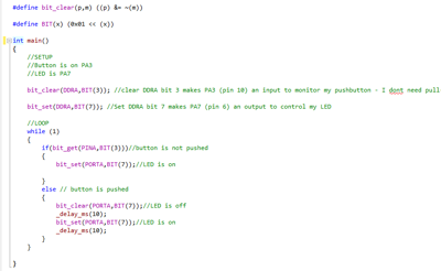
blinkas1.c program as displayed in Atmel Studio's built-in editor
/*
* blinkas1.c
*
* Created: 3/20/2014 3:24:35 PM
* Author: Scott
*/
#define F_CPU 20000000UL // 20 MHz
#include < avr/io.h >
#include < util/delay.h >
#define bit_get(p,m) ((p) & (m))
#define bit_set(p,m) ((p) |= (m))
#define bit_clear(p,m) ((p) &= ~(m))
#define BIT(x) (0x01 << (x))
int main()
{
//SETUP
//Button is on PA3
//LED is PA7
bit_clear(DDRA,BIT(3)); //clear DDRA bit 3 makes PA3 (pin 10) an input to monitor my pushbutton - I don’t need pull-up resistor
bit_set(DDRA,BIT(7)); //Set DDRA bit 7 makes PA7 (pin 6) an output to control my LED
//LOOP
while (1)
{
if(bit_get(PINA,BIT(3)))//button is not pushed
{
bit_set(PORTA,BIT(7));//LED is on
}
else // button is pushed
{
bit_clear(PORTA,BIT(7));//LED is off
_delay_ms(10);
bit_set(PORTA,BIT(7));//LED is on
_delay_ms(10);
}
}
}

Atmel Studio has the ability to read fuse settings from a microcontroller such as the ATtiny44A.

Atmel Studio also has the ability to read information about the ATtiny chip, calibrate the oscillator etc.

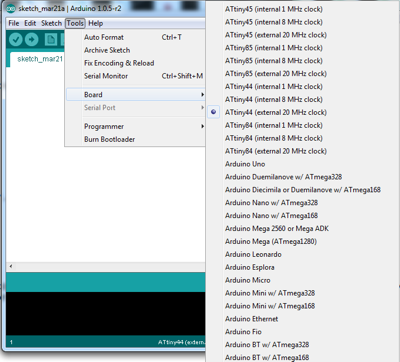
Once configured, all you need to do is pick the ATtiny44a and clock configuration from the optional "boards" in the Arduino tools pull-down menu.
/*
Blink
Turns on an LED on for one second, then off for one second, repeatedly.
This example code is in the public domain.
*/
// Pin 13 has an LED connected on most Arduino boards.
// give it a name:
// My LED is connected to ATtiny pin 6 which is equivalent to Arduino pin 7
int led = 7;
// the setup routine runs once when you press reset:
void setup() {
// initialize the digital pin as an output.
pinMode(led, OUTPUT);
}
// the loop routine runs over and over again forever:
void loop() {
digitalWrite(led, HIGH); // turn the LED on (HIGH is the voltage level)
delay(1000); // wait for a second
digitalWrite(led, LOW); // turn the LED off by making the voltage LOW
delay(1000); // wait for a second
}
Since I couldn't get it to work on my Windows 7 computer, I installed Arduino on my 64-bit Ubuntu 12.04 LTS computer
/*
Blink
Turns on an LED on for 1/10 second, then off for 1/10 second, repeatedly.
This example code is in the public domain.
*/
// Pin 13 has an LED connected on most Arduino boards.
// give it a name:
// My LED is connected to ATtiny44A pin 6 which is equivalent to Arduino pin 7
int led = 7;
// the setup routine runs once when you press reset:
void setup() {
// initialize the digital pin as an output.
pinMode(led, OUTPUT);
}
// the loop routine runs over and over again forever:
void loop() {
digitalWrite(led, HIGH); // turn the LED on (HIGH is the voltage level)
delay(100); // wait for 1/10 second
digitalWrite(led, LOW); // turn the LED off by making the voltage LOW
delay(100); // wait for 1/10 second
}
sudo gpasswd --add scott dialout <-- scott is the login account

The dreaded Arduino "did not find any USB device" error that I received in both Windows and Ubuntu.
The vast majority of my time this week was spent installing numerous Integrated Development Environments (IDE) and troubleshooting all the different problems related to installing the different toolchains. I would have much rather focused my time on learning and experimenting with the programming languages. However, now that I have several different IDE/toolchains setup on multiple computers, I should have more flexibility and be more productive on future assignments.
Programming languages:
IDE /Toolchains: