
One side with slot (constraint icons not displayed)
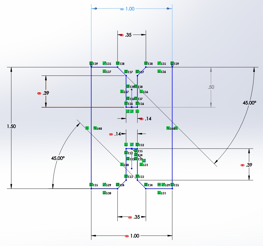
Example of connector piece showing constraint icons (green), driver dimensions, driven dimensions (grey) and linked dimensions (red).

Example of pentagon drawn using five side blocks.
The assigngment for this week is to design, make, and document a press-fit construction kit. After spending all of my time over the past two weeks sitting in front of a computer, installing software, troubleshooting, learning HTML, Mercurial, and several CAD packages, I was anxious to make stuff on the machines.
Having made many press fit projects in the past, I know first-hand how important systematic test cuts are. I also know how tedious and time consuming it is to individually adjust the width of every slot in a project design to make it the fit just right. You have to change the design to compensate for variations in material thickness and material types. Ordinarily, in non-press fit applications as long as the settings are close enough for the laser to cut through the material without catching on fire people are happy. With press fit, the laser power, speed, and frequency settings can be critical. I have even seen where just changing the color of acrylic required the slots to need re-sizing. I knew all along that there had to be a better way to make these dimensional changes. After spending time the past few weeks learning Inkscape, FreeCAD, Rhino and more I could see the potential of some of the advanced features they offer.
So my goal for this week is to make a press-fit construction kit consisting of equilateral polygons with various numbers of sides along with some generic connector pieces. Not an original idea I know, but I was most interested in making the design parametric. I wanted to be able to adjust values for the length of a side, slot width, and slot depth and have the change propagate through the design accordingly.
I spent some time testing this approach with SolidWorks to see what it would take. I was able to draw a “master” side design with a slot in it. By setting constraints, it was possible to edit the parameters and have the different aspects of the master object adjust. I found that I could then “clone” the master side and by linking the key dimensions, have all of the clones change when I changed the master. It is even possible to use formulas to determine a dimension.
However, SolidWorks is very expensive and I don’t have access to it when I am not at the college. It also has a steep learning curve and I was looking for something that the typical lab user would understand. So I decided to use FreeCAD. That is when my incredible frustration began. I spent hours drawing the design different ways trying to get it to work. I started out just sketching in 2D because I wanted the advanced capabilities of parametric and constraints but I didn’t really need 3D drawings for the laser. Whereas FreeCAD is similar to SolidWorks, it seems to be missing some of the more important capabilities that I want for this project. I read the help files, watched videos, and followed tutorials on line. Eventually I thought maybe my problem was I was using software designed for 3D to draw 2D. So I tried drawing it in 3D. I still ran into similar problems. It was hard to designate constraints that worked when I rotated the object. If I had limited my press fit parts to squares and rectangles this would have been much easier because then all of the sides would be horizontal or vertical. By default that is how most constraints and dimensions work. If I only wanted square and rectangle parts, I think InkScape, CorelDraw and FreeCAD would have worked to some extent.
For the same reasons as the angled sides, the chamfers on the slots seemed to make this much harder. It was hard to define the chamfers in a way that translated when the sides and therefore slots angle was changed. I did get closer when I started using construction lines and symmetry constraint to automatically center some features. FreeCAD also seems to be limited to what it copies, duplicates, and clones. So I eventually gave up on drawing one side and tried to draw an entire shape. To make matter worse, FreeCAD would crash at the most inopportune times. It would also lock up for long periods of time trying to find the solution for some impossible combination of constraints I had attempted.
I am persistent and didn’t want to give up. So occasionally I would stop and see if any other software I had access to would be capable of what I wanted. I tried Inkscape. The cloning tool seemed like it would work well. Unfortunately, Inkscape is better suited for free style illustration that the precise CAD drawings I was trying to make. It was not dimension driven and did not allow for constraints to control how it should react to changes.
I then went to my old stand by CorelDraw. I didn’t know that CorelDraw had a clone tool until last week. However, it does not work very well. The command is in a pull down menu and only works once. To use it again, you have to reselect the master and find the command under the pull down menu. The biggest problem is that if you change a clone, it disables the link to all related attributes. For example, in my case if I rotate a clone of the master side object, changes to the master no longer effect that clone’s rotation or side. It defeats the purpose of what I wanted to accomplish. Interestingly, changes to the master’s fill color, line thickness, etc. still change the clone.
I think Rhino could do what I want, but I don’t have Rhino where the laser is and the demo version will only let me save a limited number of times. I didn’t want to get it done with Rhino and then not be able to use it or save it. Another option would be Kokopelli but I haven’t been able to get it to run due to an OpenGL or video driver issue.
So I spent an entire very long day working on this and have nothing to show. By now I could have easily saved time and effort manually redrawing the changes several times instead of making something parametric.
After a frustrating day of not accomplishing what I wanted using Inscape, CorelDraw, of FreeCAD, I used SolidWorks 2012.
Design:
One side with slot (constraint icons not displayed)
Example of connector piece showing constraint icons (green), driver dimensions, driven dimensions (grey) and linked dimensions (red).
Example of pentagon drawn using five side blocks.
Laser Cutting:
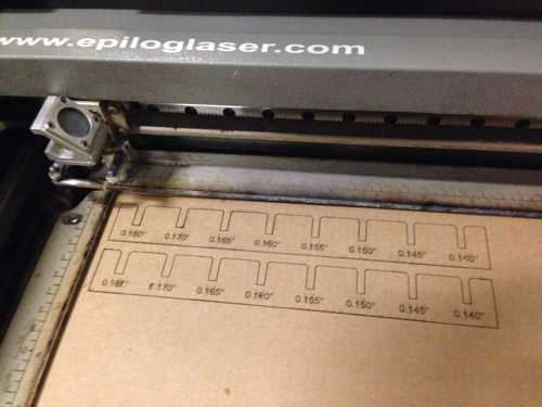
The first test strips did not get completely cut out.

A problem with the air assist caused the cardboard to catch on fire and burn the edges.
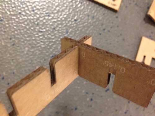
A test strip makes it easy to determine just the right slot size without a lot of trial and error.
Just the right laser settings for a clean cut all the way through without any burning.

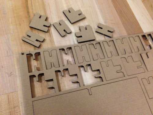
This is the carcasses of cardboard from all the parts I cut.
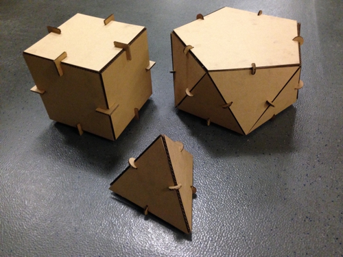
The parts fit together snuggly and it was fun to see what 3D shapes I could assemble.
Project Files: