wk6 | electronics design
Assignments :
- redraw the echo hello-world board
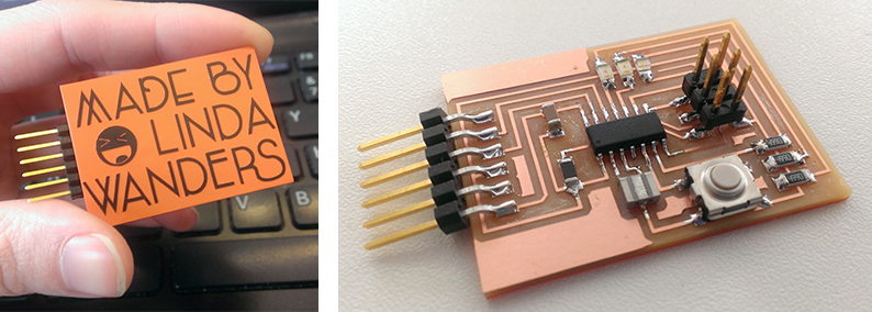
- add (at least) a button and LED (with a current-limiting resistor) to the new design
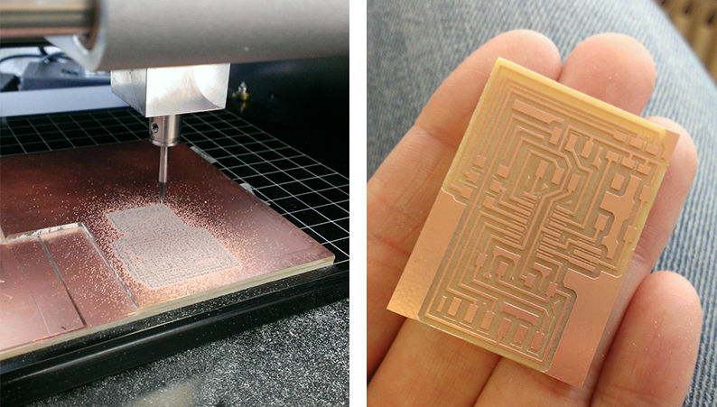
- check the design rules, and make it (mill it - stuff it - test it)
Download : eagle schematic & board - button & blink
My notes :
7 march 2014 | About Eagle
- https://learn.sparkfun.com/tutorials/how-to-install-and-setup-eagle/all
- https://www.youtube.com/watch?v=1AXwjZoyNno (jeremy blum about eagle)
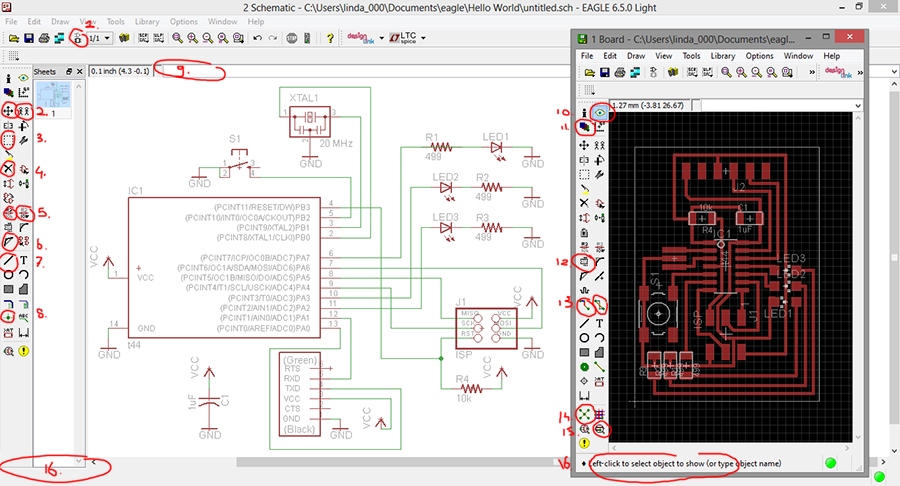
- Switch between schematic & board.
- Move tool & copy tool. When eagle isn't sure about which part you clicked, it will ask at the bottom of the screen (nr 16).
- Group tool. (again, look at bottom of screen to confirm eagle's questions).
- Delete tool.
- Renaming tools. Use these 2 tools to rename the parts you've placed in the schematic (short names are good).
- Split tool. For when you want to bend a straight drawn wire at an angle.
- Wire tool.
- Junction tool. For when 2 wires need to be a junction (splitting) not used crossing over each other.
- Type commands here (like 'add').
- Show tool. Use this one to to click a path, it will light up, so you get a better view of how it's linked.
- Layer settings.
- Smash button. If a name of your component is falling of the board design, you can relocate it.
Good housekeeping is having all you names on the board. (readable & good placement = no errors occurring). - Routing (and de-routing) tool.
- Ratsnest tool. Use it to get the yellow helper lines to reroute, after you moved your component.
- DRC. Button to check your design rules. (can load and save via this button here as well).
10 march 2014 | Setting up eagle for the first time
step 1 : (After installing it...) First time start up eagle asks you to define a place when it can store future files.
step 2 : Download the library needed. (fabacademy library).
Put the file's in the defined eagle folder. (in my case: in documents folder).
step 3 : Turn off all the regular library's (don't want to see what you don't use).
Eagle library's folder > right click, choose 'use none'.
step 4 : Load the library's you do want to use.
Fab.lbr > right click > use.
regular library add > supply
regular library add > led
step 5 : make a new project
projects > eagle > right click > new project (and name it).
Double click to open.
step 6 : (Like in cmd) use typing to command. (in the bar in center top of the screen).
Type 'add' + enter.
In this new popped-up 'add' screen, find the 'tiny 44'.
Click ok and click again to place it.
continue collecting all the parts needed.
(example board:
http://academy.cba.mit.edu/classes/embedded_programming/hello.ftdi.44.png)
- IC1 t44 > micro controller
- xtal1 20 MHz > resonator > (the difference: a crystal has 2 legs, a resonator has 3)
- R1 10k > resistor (in dutch: weerstand)
- C1 1uF > capacitor (in dutch: condensator)
- J2 FTDI > connector (or called jumper)
- J1 ISP > (the one with the 6 pins)
After placing your parts, also place a vcc and a gnd (from the supply library).
step 7 : Use the wire tool (from the toolbar) to connect al the parts.
Click on starting point once, click once more if you want the line to continue at a different angle, double click to close.
step 8 : When done with the basics, add a button, led and resistor on the board.
Because the micro controller has 3 legs left to use, I decided to put on 3 led's in stead of one.
This also means I need 3 resistors, one for each led.
11 march 2014 | Adding LED & calculate which resonator to use
When placing a LED, it also needs a resistor.
Check the datasheet of the led to calculate which resistor you need.
note: every colored led has a different datasheet
http://en.wikipedia.org/wiki/Ohm's_law
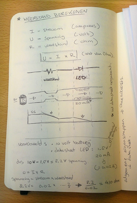
Law of Ohm : U = I x R (spanning = stroom x weerstand)
I = Ampere (stroom)
U = Volts (spanning)
R = Ohm (weerstand)
Red led :
http://www.digikey.com/product-details
Datasheet : http://optoelectronics.liteon.com/_ltst-c150ckt.pdf
info from datasheet : Forward Voltage > 20mA and the Typ. > 1.8
Step 1 : Start with calculating how much volt is left after it went trough the resistor:
5V (starting point is the micro controller) - 1.8V (the resistor) = 3.2 Volt
Step 2 : Calculate U = I x R (Volt = Ampere x Ohm)
Translate the 20mA to 0.02A.
3.2V = 0.02 x ...?
(switch the numbers around to get the right answer, like c = a x b).
3.2 / 0.02 = 160 Ohm.
To find which components are available in the fabLab > check the inventory :
https://docs.google.com/spreadsheet/pub
http://www.digikey.com/product-detail/en/LTST-C150GKT/160-1169-1-ND/269241 | 160-1169-1-ND |
LED GREEN CLEAR 1206 SMD | FV 2.1 = 20mA
http://www.digikey.com/product-detail/en/LTST-C150KFKT/160-1403-1-ND/386757 | 160-1403-1-ND |
LED YELLOW ORANGE CLEAR 1206 SMD | FV 2.0 = 20mA
http://www.digikey.com/product-detail/en/LTST-C230TBKT/160-1889-1-ND/3306146 | 160-1889-1-ND |
LED BLUE CLEAR 1206 REV MT SMD | FV 3.3 = 20mA
11 march 2014 | Making the board
step 1 : route the board.
After completing the schematic drawing, switch to the board design.
Place all the parts where you like them to be, and draw the routing lines.
(use the ratsnest tool to get the yellow helper lines to be less chaotic.)
step 2 : When happy with the layout, you check the design rules (click the button in the toolbar).
Here you can set up the rules, (also load it/save it).
These rules will check for you if there are any design flaws in the layout of the board.
(The settings are about the width of the cutter head, and general setting of (in my case ) the Modela.)
step 3 : If any error occur, troubleshoot them.
Edit the design of the board, till no more design rule messages appear.
When done you can change the white outline around the board design to the desired (as small as possible) size.
step 4 : make the png files (at 1200 DPI, monochroome).
(one of the traces and one of the board outline).
Use the layer button in the toolbar to toggle the views correct for the exporting.
File > export > image.
Open up the board png in a pixel program (like paint).
Fill up the center of the board with white pixels, and save it.
(this makes sure that the Modela will cut around the outline of your board).
Step 5 : Mill the board & solder the components.
(And check for shorts.)