Week 7 - Make Something BIG!
Brief
The brief for this weeks assignment was to learn how to use the Shopbot, and design and build something big.
Testing - "Active Hinge"
In this project was keen to try and use the active hinge that has been experimented with in the all labs around the world. In Mancester we have only successfully used the hinge on the laser cutter and I wanted to scale it up and make it work on the Shopbot.
From making the joint on the laser I know what pattern of cutting works well for 3mm birch plywood, but the challenge was to make it work using a cutting tool and on the much more rigid 12mm birch ply.
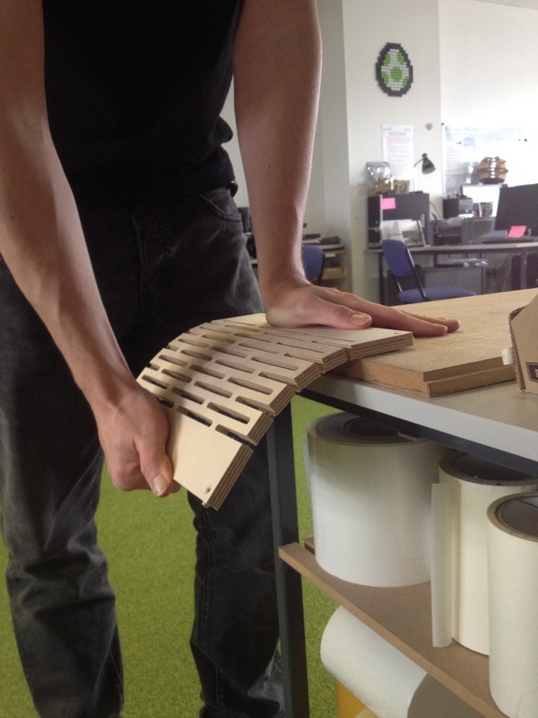
Initially I drew out a cut pattern in Partworks 3.5 and used cutting on the line with a 6mm dwn cutting tool to carry out the first test.
Here is the result
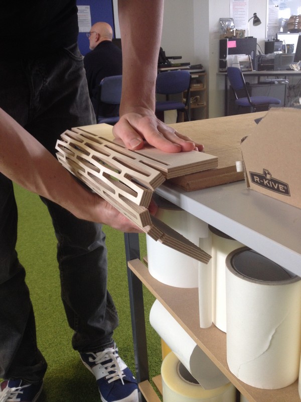
Not nearly enough flex, so I adjusted my drawing in a couple of key areas and here is the result.
So what made such a big difference?
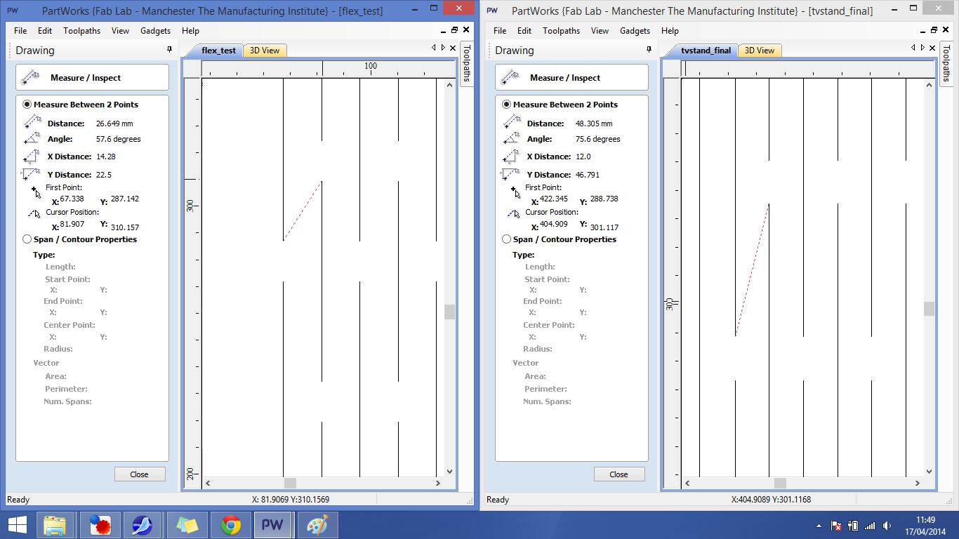
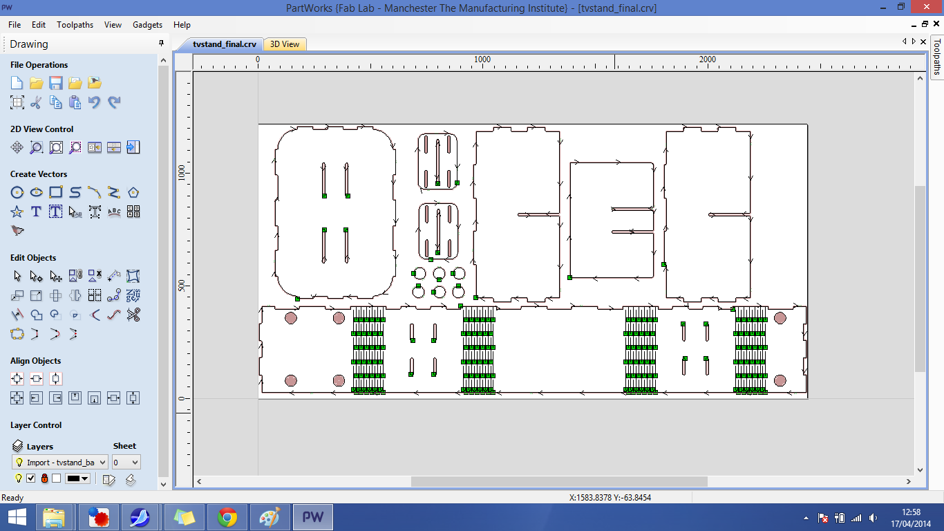
Here are the toolpath drawings together showing the differences
The first adjustment was to distribute the pattern evenly ensuring the y-axis measurement shown is equal at each point of the drawing (this was a mistake in the first drawing). The second adjustment was to change the gap between the cutlines to 12mm. A 12mm gap when cutting on the line with a 6mm tool makes a gap to material ratio of 1:1. The combination of these adjustments made a big difference to the flexibility of the hinge. I used the final test design in the toolpath creation for the tv stand.
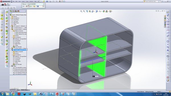
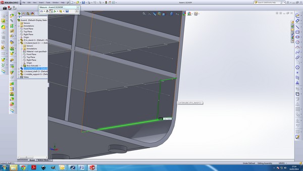
Design of TV Stand - SolidworksI chose to design a TV stand for my new house. I designed the concept in Solidworks as separate parts in an assembly, which allows me to check that each piece will fit together and then export each part as a drawing that can be used to set up toolpaths in Partworks.
Milling
As I had 1 long piece that spanned the full length of the shopbot I had to be extra careful when thinking about anchor points for the workpiece and the parts.
*TIP* When positioning tabs, ensure you are anchoring to material that will still have some strength after the toolpath has cut out all the pieces. Always choose to tab to large areas of left over material when possible and if there are only a few places to put tabs on a large part, beef up those tabs so they they have more strength. Lastly if in doubt add more tabs, the time taken up by cutting and sanding a few extra tabs is nothing compared to the time & cost taken when under-tabbing causes a ruined workpiece and often a broken milling bit.
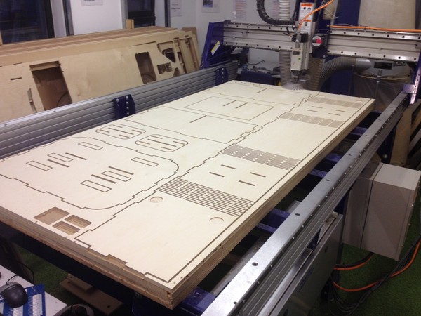
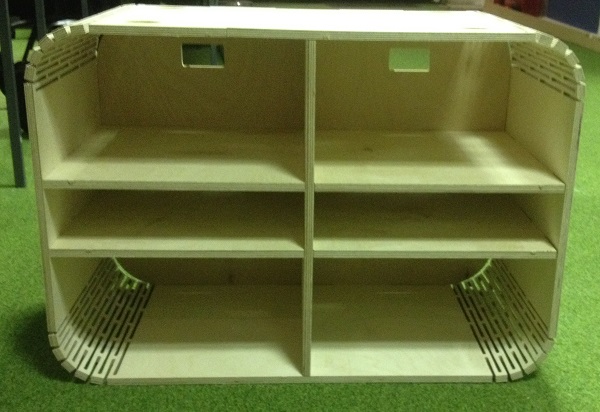
3 hours later on the Shopbot and I was here.
*TIP* When cutting 12mm plywood on the Shopbot you are best trying to anchor the workpiece at 6 points to keep an even surface depth over the bed. Ensure that placed screws will not come in to contact with any toolpaths. To do this the best way is to plot coordinates on the partworks file and use 2 measuring tapes to mark out and place the screws. DONT MAKE THE TOLERANCE OF YOUR MEASUREMENTS TOO TIGHT. As a rule I allow for 2 tool diameters of error in my measurement which ensures you won't run into any screws.
*TIP* When machining plywood you should always use a down cutter to get a better edge finish. Using a down cutter does mean you get a worse bottom edge and to combat this you want the scrificial bed to be touching the workpiece in all areas. As this isn't usually the case with the standard bed of a shopbot, I used a new sacrificial layer of 3mm mdf to get the best finish possible. Alterntively you could surface the bed to get rid of all cut areas but this may be a longer process especially if the bed has large holes in certain areas. I would only use this method with plywood parts, when finish is a very important factor.
Finishing & Assembly
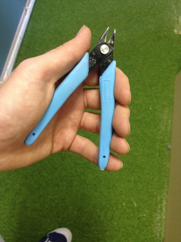
I cut out the tabs using a pair of garden snips.
I always try and cut close to the workpiece so I have less material to take off when filling. Next I filled the tabs down, ensuring to file the tabs off downwards (flip the part over after milling) this will help stop any tearing/ripping of the wood into the workpiece.
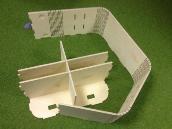
Now for the assembly
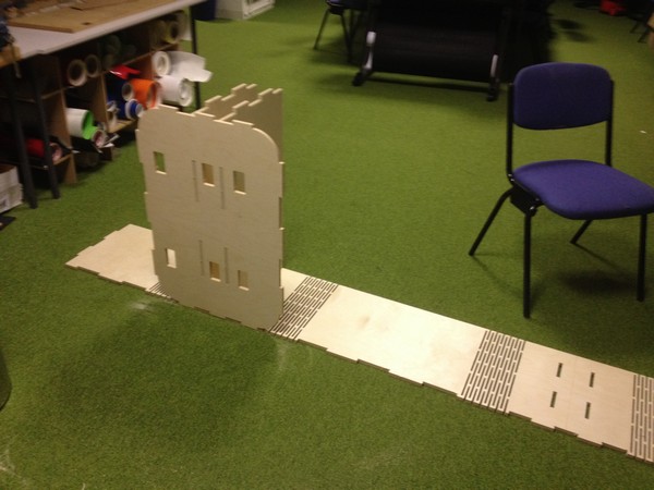
Half cuts slide in without using a hammer, and the finger joints also push into place, now for the difficult wrap around.
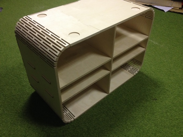
After trying a couple of ways I found this method worked best.
I used wood glue on the finger joints and left overnight. Due to the size of the pieces I couldn't use trigger clamps to hold the pieces together so I used a combination of heavy objects and table legs to restrict movement as much as possible.
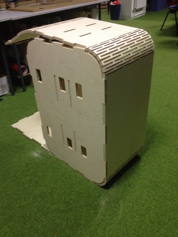
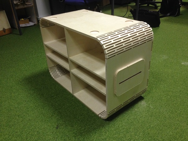
Final result
The radius of curvature on the hinge sections doesn't perfectly fit the radius on the back. If i were to re-make this I would look at trying to get that to match up better. Having said that it is at the back and will not be easily seen when in place.
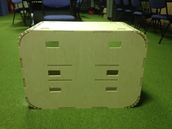
The caps you see on the sides hide the finger joints that come through the side from the shelves, and make quite good handles for lifting. I chose to add these to the design when I realised I couldn't use pockets (hidden joints) as I was machining the other side. When machining with a down cutter you always get a better looking top edge and that edge I wanted to face out on the wrap-around piece. I therefore extended the width of the finger joints on the shelves to make them protrude out past the sides and then I attached the caps to these pieces using pocket areas to create hidden joints. This is the first time I have used this method to hide finger joint and I think it works nicely.
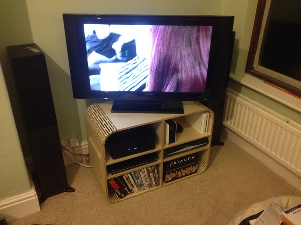
Final result - Update - Taking it home
I used a non-yellowing polyurethane coating to protect the tv stand (2 coats, painted on). This left me with a slightly rough finish on the wood. I think if I were to redo this I would choose a stain/varnish instead.
It fits perfect in my house. The sky+ box is pretty snug so I'll see if I get any overheating issues and report back.
Downloadable Files + Settings
Partworks 3.5T
DXF
Cutting tool: 6mm down cutter
Feed rate: 3 inches per second
Pass rate: 3mm
Plunge rate 1 inch per second
Ramp: On - 15mm