Week 13 - Networking and Communication
Brief
The brief for this weeks assignment was to make a network which gets one processor to talk to another.
PCB Making
As I am a complete beginner when it comes to networking/programming and electronics I decided to make the example serial network communication between a bridge and 2 nodes.
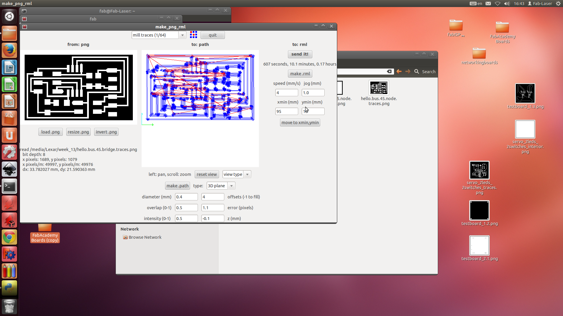
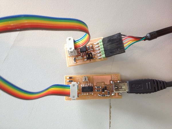
First step was to mill the boards. I used the PNG's available on this weeks academy page and milled out 2 node boards and 2 bridge boards. I chose to mill the extra bridge board as it would fit nicely on the small pcb stock and if I had an error with a board I'd have a spare ready to use. I milled the boards using fab modules as usual, and they all milled successfully first time.
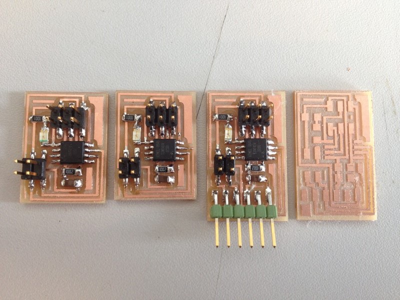
I then soldered the components to the boards.
Hopefully I won't need to use my spare board but I'll find that out at the next stage - programming.
Programming
To program the boards I followed this great tutorial.
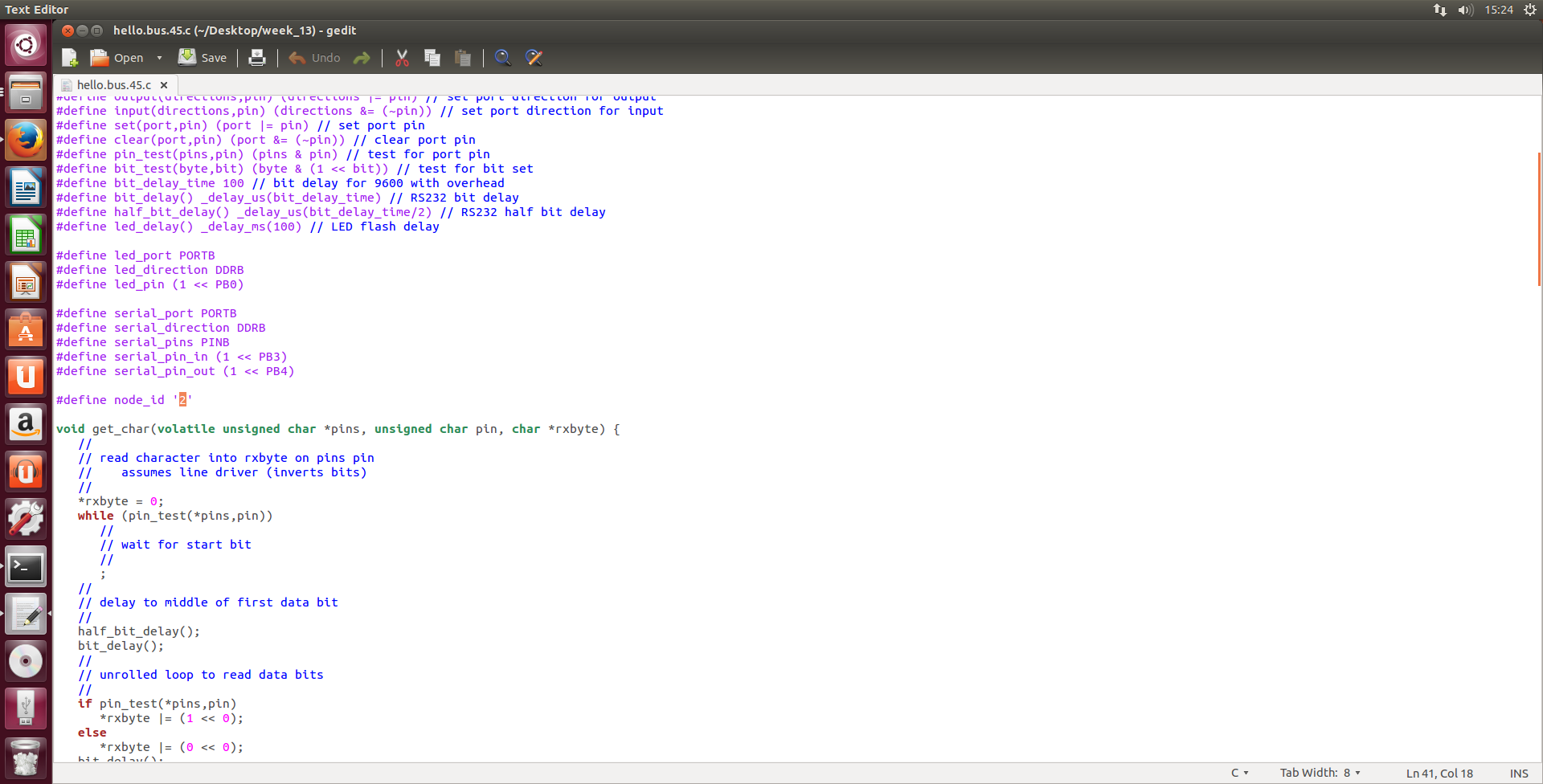
Firstly I downloaded the make and c file from the academy page. Next I opened the c file in text editor and when needed changed the node label to "0" then "1" and finally "2" to program the bridge and then each node separately.
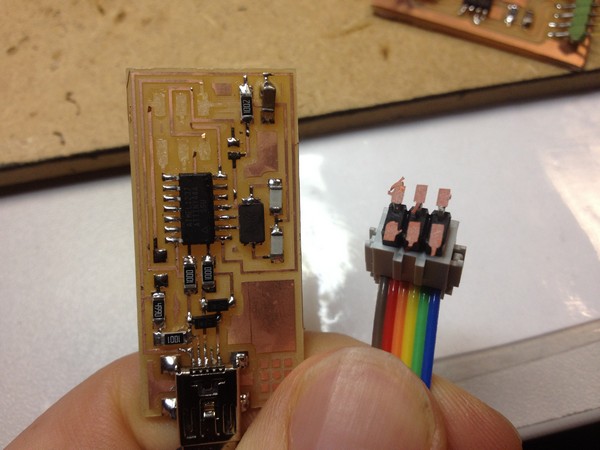
I programmed using my newly made FabISP. My old FabISP's tracks lifted and I was left having to re-make the board.
Happily my new ISP worked well and I programmed each board in turn successfully.
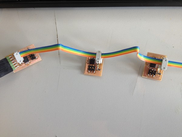
I then connected up the 3 boards using a 4 wire cable I made as shown in the tutorial.
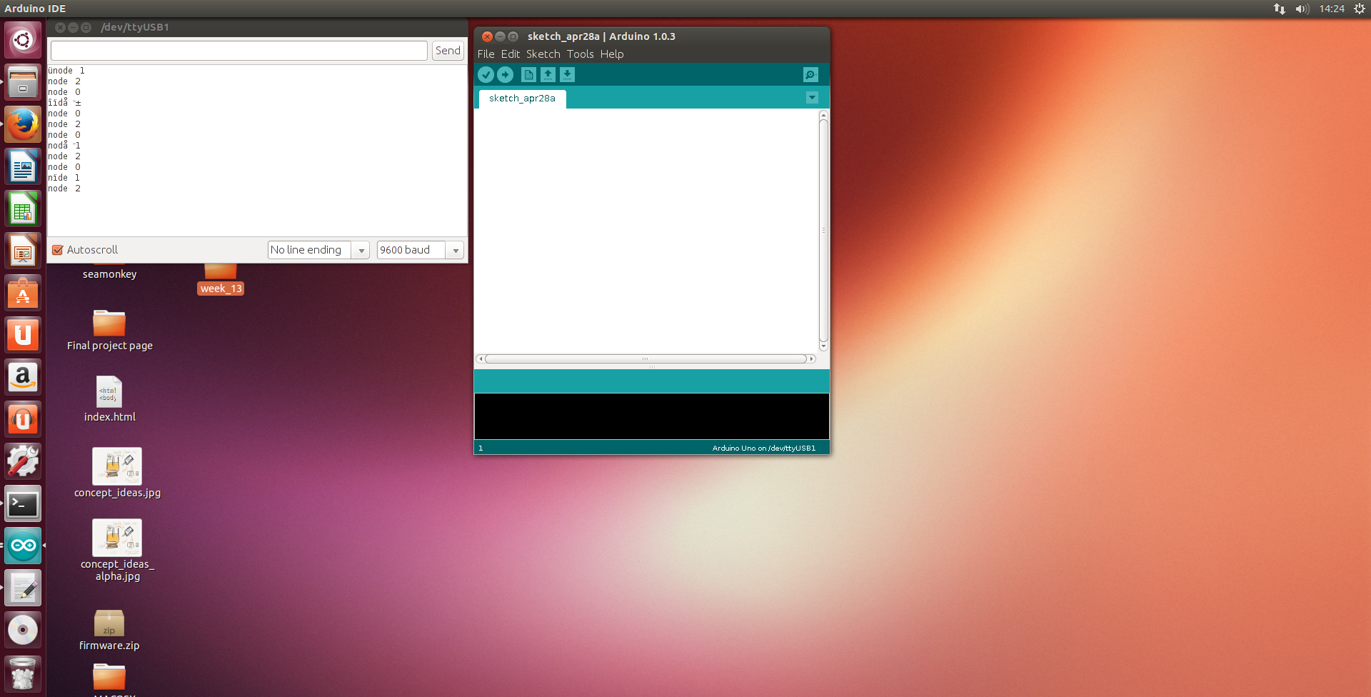
Next I tried to run the python script in Ubuntu to use serial the command returned an error of "no device in this location" At this stage I chose to use the Arduino IDE serial monitor instead.
I initially found my serial monitor to be greyed out and it seemed like my serial connection was not being seen. After considering a permissions error I looked around and realised that as I am running Ubuntu in a virtual box I had made the rookie mistake of not enabling the usb device in the virtual window. After enabling the serial monitor was selectable in the Arduino IDE. I tested the program by inputting 0-2 in serial and the boards acted correctly flashing once in unison and then individually to identify each node entered in serial.
I went back to try the python script with the properly enabled FTDI lead and found that although the window did load I could not input values into the window. Next I want to look carefully at Neil's code and try to understand what is happening within the program.
I will look further into the possibility of using this transmit and receive serial networking system in my final project.