Week 10 - Input Devices
Brief
The brief for this weeks assignment was to design, make and program a board that uses an input device.
Temperature Sensor
An input device that I plan to use in my final project is the temperature sensor (to sense and control the brewing environment) and therefore it seems the perfect choice to try and learn more about how to use it.
Circuit Design
I am still quite early on in my use of electronics and so I used Neil's board layout as a basis for my own. I went through the process of creating a board schematic using Eagle and laying out and routing the board in the board layout window. I experimented with round cornered tracks as oppose to perpendicular tracks.
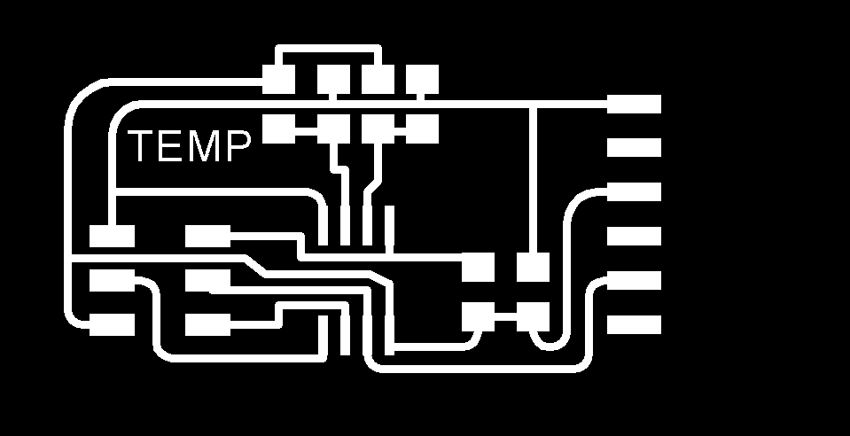
*TIP* I found some useful parts in Eagle which help identify areas for track routing. Writing "show X" will highlight the connection"X" in the board layout window. eg show vcc. Also when routing traces underneath a resistor juntion use the "change width" command to take the traces down to 0.016" instead of teh more widely used 0.024". Finally after typing a command into the console you can use the familiar UP Arrow keyto cycle through previously typed commands just like you can in an Ubuntu terminal window.
This can be a very helpful instruction to ensure all chips and connectors are rotated and aligned correctly before starting the difficult task of circuit routing. This circuit is fairly straight forward but from looking at other boards designed by Neil I an starting to appreciate the effort that goes into laying out a board efficiently. The key part seems to be to use resistor and capacitor jumps effectively to route traces underneath the junctions and get away from
the need for jump wires.
To create the cutout file for the board I followed the usual routine.
- Export dimension layer to monochrome png 500dpi.
- Open in Gimp
- Fill in white marked areas using the paint tool
- Expand canvas size by 20px (link dims) and center
- Flatten image to create a black rectangle with a white border
- Value invert to create a white rectangle with white border.
*TIP* Remember to dd the same pixel amount to the traces board to ensure all parts match up, and remember, the white area is maintained and the black area cut so always invert the interior png otherwise you might cut through your tracks.
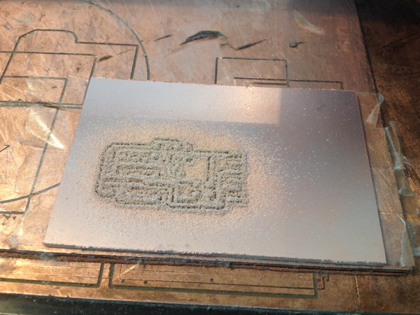
Milling the board
The modella was used to mill out my board. The same process was followed as in previous weeks, with extra care spent on laying tape without bubbles and applying pressure to the board using the stiff sponge from the vinyl cutter section.
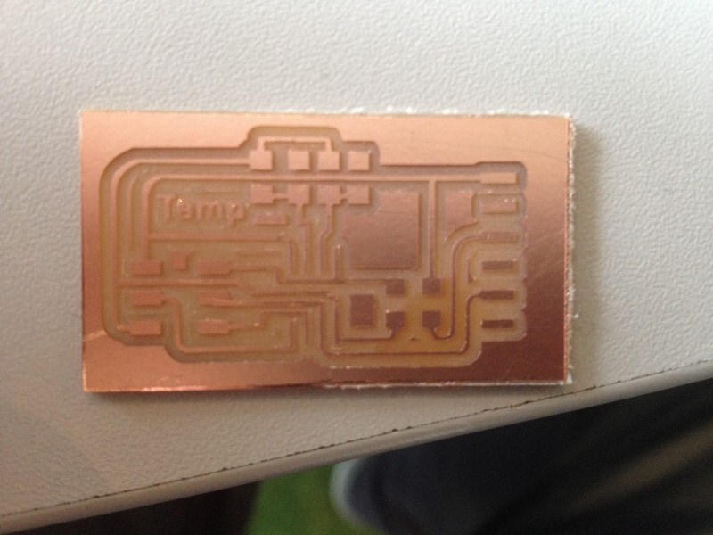
The board came out well. I soldered it and then programmed it using Neil's C code. I programmed the board from Ubuntu and then ran Neil's Python script to check the board.
This circuit uses a 10K NTC Thermistor in a bridge with 3 other 10k resistors. The thermistors resistence changes dependent on temperature and therefore causes a voltage differential in the bridge. The differential value is then converted to a deg c number using some maths in Neil's Python program.
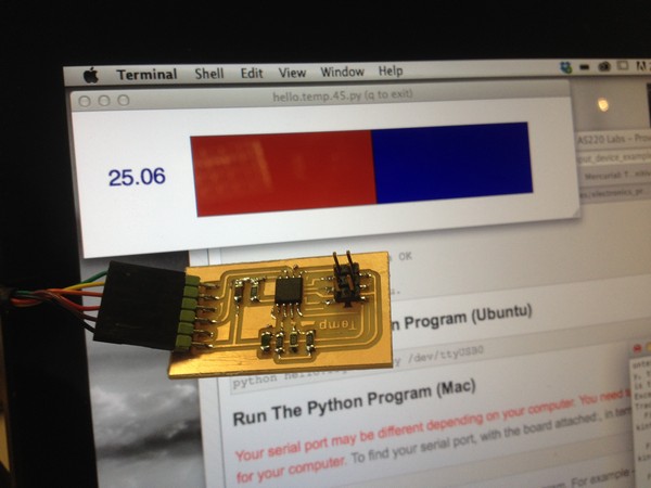
Initially i found my board unresponsive and the python program jumped around a lot and didn't proportionally increase its output value when blowed on with warm air. I did infact re-check the circuit diagram and mill out Neil's board for comparison to try and fault-find on my board. It was mentioned by David (my tutor) that the tracks were thinner on my board than Neil's but apart from that it was exactly the same. Eventually the problem was solved by changing the bit-delay time from 100 to 104 in the .c program. This was brought up in the lecture but It took me making the board 4 times to find the solution.
Eventually I was able to use the board that I had created with the python script and got a good response when I heated up the thermistor with my thumb, and blew on it with warm air.
This working circuit is a good base for my final project which will need to utilise at least one temperature sensing circuit.
Downloadable filesthermistorTraces.png
thermistorInterior.png
Eagle board schematic
Eagle board layout