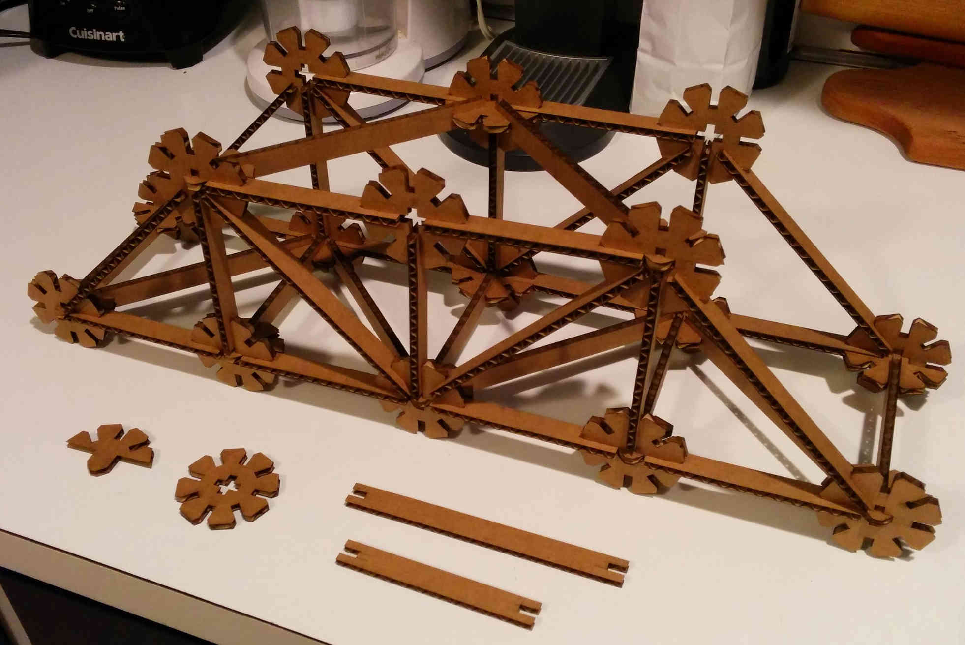
I designed a kit to build trusses. The kit consists of four unique pieces: leg, diagonal, wheel and half-wheel. The wheel has notches every 45 degrees with a cross-shaped hole in the center that will accept legs or diagonals or the tab on the half-wheel. The diagonal along with two legs and an assortment of three wheels and half-wheels form a 45 degree right triangle. A set of sample pieces with an almost complete bridge is below:
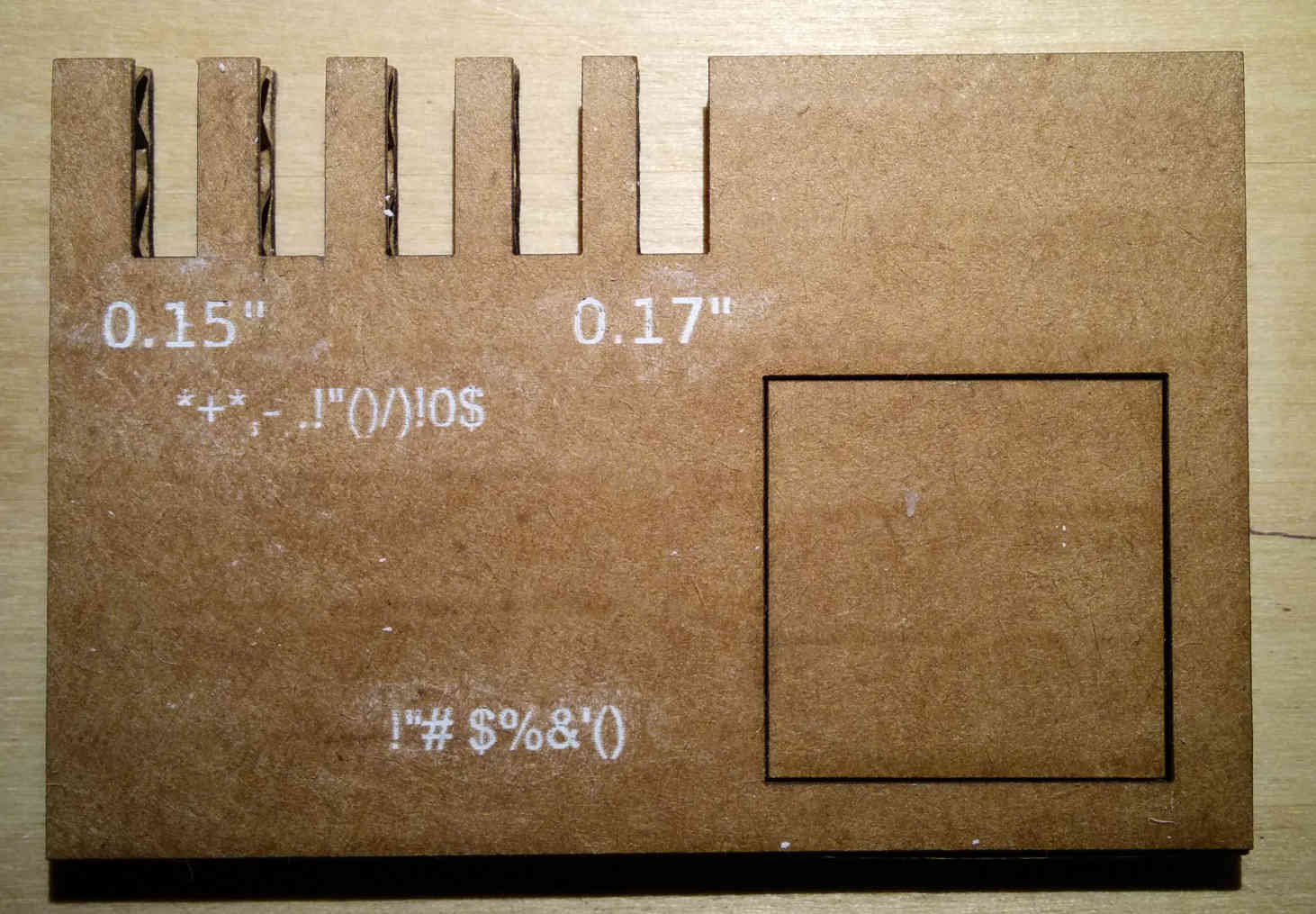
The gauge has two features that I used in the lab to adjust my
design--the series of notches on the top left and the square cut
hole in the lower right. The gauge of 5 notches, each in
0.005"increments, as drawn in Inkscape. Using two gauges, I choose
the best pairing that felt right for the press fit (0.155") and
adjusted the notches in my basic shape. The square is a 1 inch on
side, again as drawn in Inkscape so that the kerf can be
calculated from the difference between the inner and outer edges
(divided by two). From the parameters I used throughout this
process, I think that the kerf was 0.011 inches. I used the
measurements from the square to size the tab and corresponding
cross-shaped hole on the half-wheel and wheel respectively.
The lettering on the gauge was engraved from a 12 point font
applied to the design. I forgot to convert two text strings to
paths and the result were the two garbled pieces of texts
(translated are '0.005" increments' and '1 inch square'). The
white color I owe to my son, who showed me that an eraser can
remove crayon. I applied the crayon in many directions to fill the
text and erased.
When I settled on the notch design, I redesigned all of the
parts. The leg and diagonal are simply rectangles with a centered
notch on either end and the wheel is a base circle with four
notches aligned in the basic directions than I took a copy of the
whole thing (grouped), rotated it in place by 45 degrees, then
removed the inner circle and connected the ends of the notches to
each other. The first version of the half-wheel was just a
bisected wheel with a tab. Of course now it sounds easy but the
first iteration (with the guesstimate notches--printed paper glued
on cereal box board) was the dry run for getting the work done
efficiently (once I abandoned my parametric aspirations).
With the base part designs complete, I cut out five pieces with
the laser cutter. I used the laser cutter with the settings for
cardboard and was satisfied with the results so I didn't see the
need to tweak the parameters. When I did the test fit, I found two
problems with my design. The easiest was that the notch depth on
the legs and diagonals was too deep, by about the length of the
chamfer, so I eliminated it from both pieces. From my experience
with the gauge, I found that I didn't have very much trouble using
cardboard with non-chamfered notches. The second problem was with
the design for the half-wheel, the tab did not extend enough past
the surface of the wheel which allowed too much motion in the
joint and a weird shoulder configuration due to the (now
recognized) ham-fisted biesction that interfered with the ends of
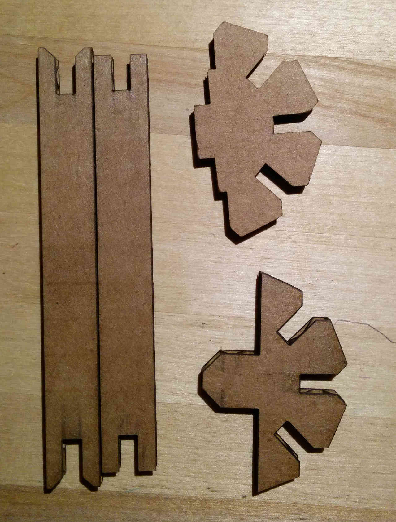
the legs and diagonals. So I added length to the tab and I
simplified the shoulder and moved it to allow more room. The next
figure shows the difference in the parts.
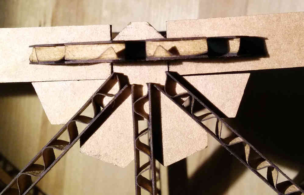
The final result is a much better joint, the half-wheel joint is
more rigid and the legs fit better in the joint. The following
figure shows the final joint: