Schnyder - Final Project: An Optical Absolute Rotary Encoder

I will build an optical absolute rotary encoder for my final project. This rotary encoder will convert the angular position of an acrylic disk to a digital code using LEDs and light detectors and engravings on the disk.

This project developed from my previous final project to build a teach-yourself-to-tell-time analog clock. The object was to allow a child to set the clock (the hands would be tied together like a regular clock) and then press a button then electronics would deliver the time audibly. The focus of the problem quickly became how to store the time in the electronics from the mechanical input. The clock had to tell the correct time from the moment that the child first presses the button. An hour hand has 720 discrete positions for each hour and minute combination in a 12 hour cycle--in other words, a resolution of 0.5 degrees. There were many options to choose from but in the end I chose an optical rotary encoder.

Typical rotary encoders use binary values. I want to explore controlling the light levels to add different number systems. As the base increases (number of discrete light levels) the total number of positions (transmitter-receiver pairs) decrease. The following chart shows the minimum combinations in order to produce at least 720 positions.

Base/Discrete Light Levels
Positions (Transmitter/Receiver Pairs)
Combinations
2
10
1024
3
6
729
4
5
1024
5
5
3125
6
4
1296
7
4
2401
8
4
4096
  

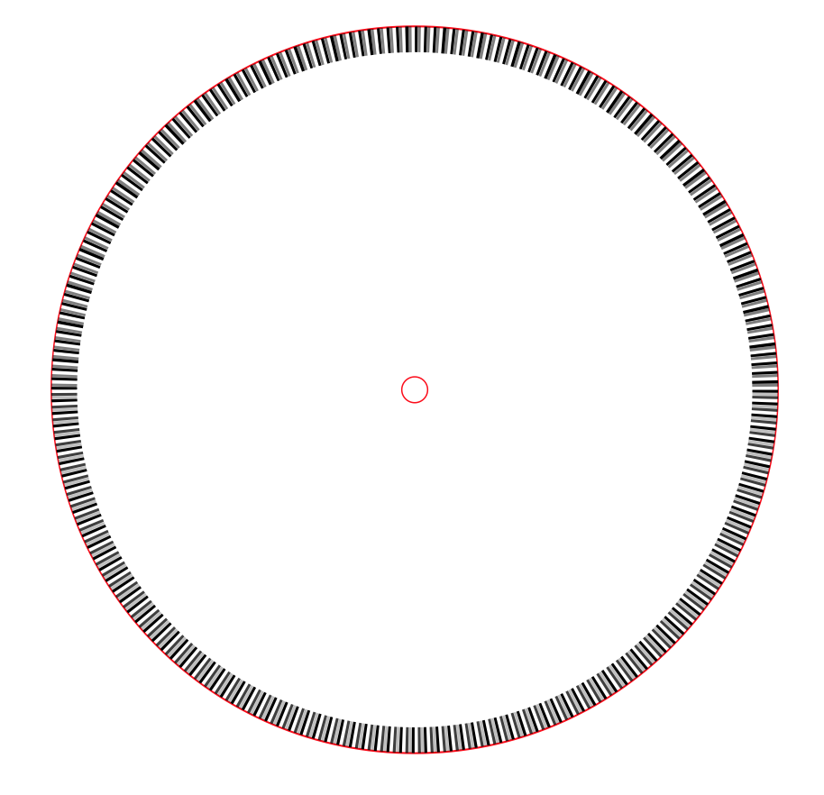
I narrowed my choices to exploring bases 3 and 4. I set up a test pattern on an acrylic disk using 0%, 33%, 50%, 67%, & 100% gradients of white-black. The test pattern was a band on the outer edge of a 7 inch circle and half of the circle had a three-gradient pattern (0%, 50%, and 100%) and the other half had a four gradient pattern (0%, 33%, 67%, and 100%). There were 720 positions in this band and the band was 0.25" wide. This is an image and an enlargement of a section of the file used by the laser cutter to engrave the disk. It is important to note that the test pattern is only one of five or six bands that will be used for the final disk.

Sample WheelWheel Closeup


I successfully cut/engraved a clear, acrylic disk on AS220's laser cutter using the following values:


Speed
Power
Notes
Raster
100
40
600 dpi
Vector
15
100
5,000 Hz


I mocked up an LED board and a light detector board to an Arduino UNO to do some basic testing. The LED was on one side of the disk and the detector was on the other.  Using a jury-rigged mechanical system, I was able to see the variations in the light levels as I passed the disk through the beam. Unfortunately, I was holding the disk in my hands so accuracy and precision were not present during the trials and it was difficult to distinguish when the light was passing through the different gradients.

Here are the next items to investigate/complete:

1. Build a better system for holding the components, especially the disk.
2. Improve data capture. Change resistance, sample rates, add recording feature.
3. Investigate reflective light rather than pass through.
4. Investigate painting the disk or using acrylic that has a thin opaque outer layer of a different color (maybe reflective coatings).
5. Vary gradient levels to find best contrasts between levels.
6. Build better electronics using components from the Fab Inventory.
7. Build the final disk.