NETWORKING AND COMMUNICATIONS
Goals:
Design and build a wired &/or wireless network connecting at least two nodes
At the lab
I was waitig for this assignment for many weeks. I wanted to make a couple of things for this assignment: one is building a wireless network using the radio existing boards. The other is connecting two nodes in a master-slave mode.
Radio Board:
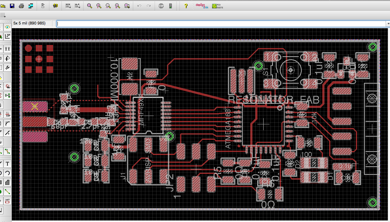
I wanted to use a radio board protocol to test how it works. In order to make that I redisigned the hello radio board and I add a 6 pin header to it for attaching my future accelerometer board.
So the first thing is designing the board with Eagle. It was not easy to find the correct place to deploy the 6 pin header but after few tries I could based it. As you can se the radio chip and the ATMEGA 328 get a bit separated now but nothing important for the entire functionality.
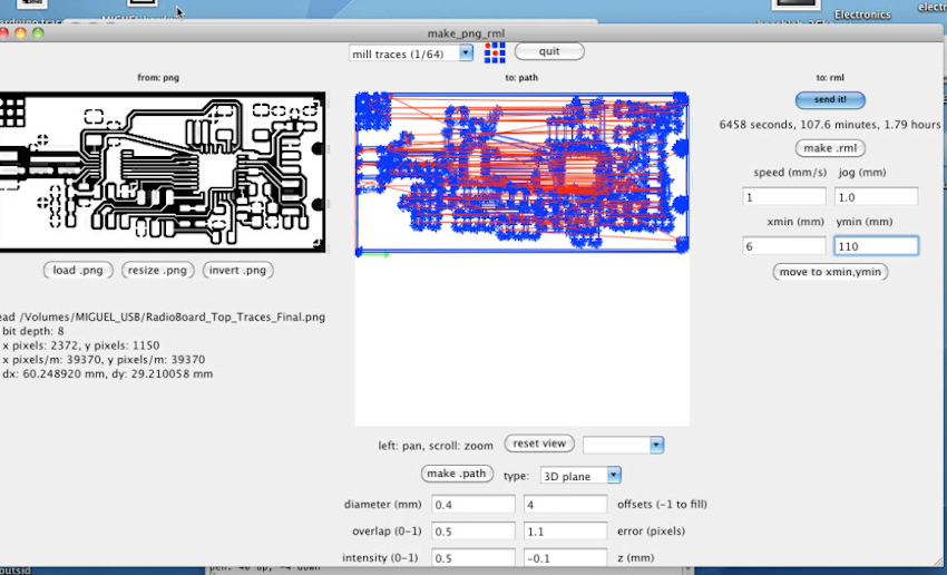
After that I start milling the board which it was very painful: something went wrong fex time with the modela and I had to try many times before It milled well. At the end it was a matter of giving enough value to the Z axis in the Fab Modules. The Bit when it goes deeper it works better.
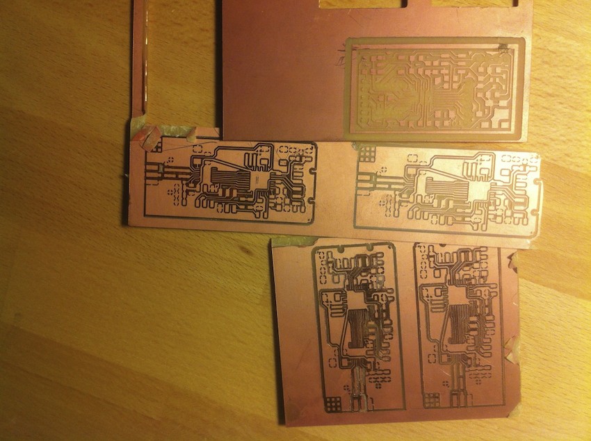
This is the amount of useless boards I got to do before having the final result:
Now it's time for stuffing the components and starts the “funny” part: I never solder such a tiny components. It was one of the most difficult things I had to do with my hand in my whole life. Also my eyes hurt a lot after spending hours and hours stuffing the components.
They were so small that I could barely sustain the component with the tweezers.
After some suffering the result is the following:
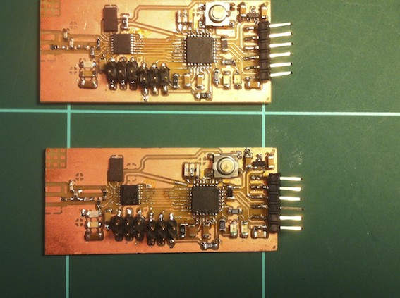
Unfortunately the last part of it is to make them work. And there is where I find my trouble: it is impossible to boot loader it. There is always a connecting error and I don't know what is wrong. I made a check list of fails and everything went ok, so I don't know what to think. For the moment I leave it on stand bye and maybe after Fab Academy I try to resolve it. It's probably a soldering mistake, or maybe one of the small components has burned while soldering, but I can not find the mistake.
Master Slave
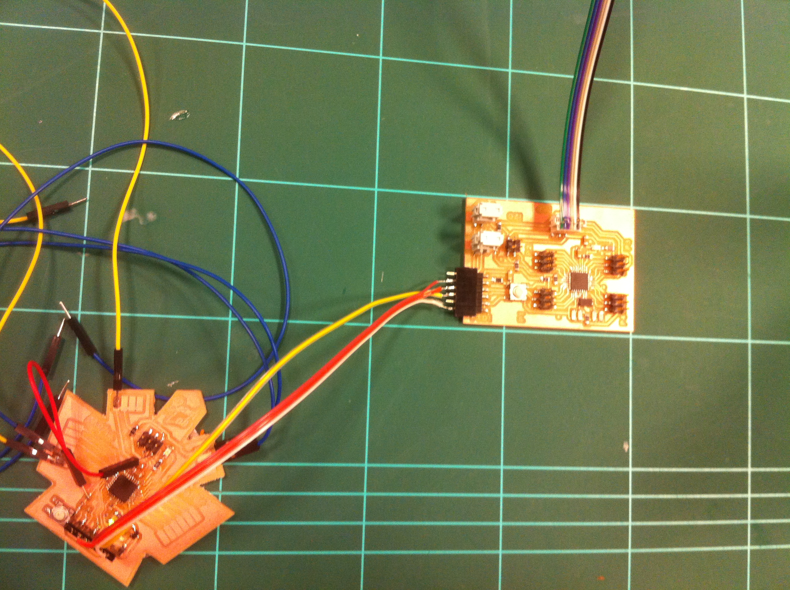
So I start again a new networking assignment, this time is a Master Slave protocol between two nods.
In both board I'm using are Arduino based ones, one is my design and the other is Andrews Leek design.
What I did creating this protocol is making blink the number pin 13 (LED) ON and OFF with a certain delay between blinks.
I made the script on Arduino IDE for the master and slave. I program my board into master and the Andrew's one into slave.
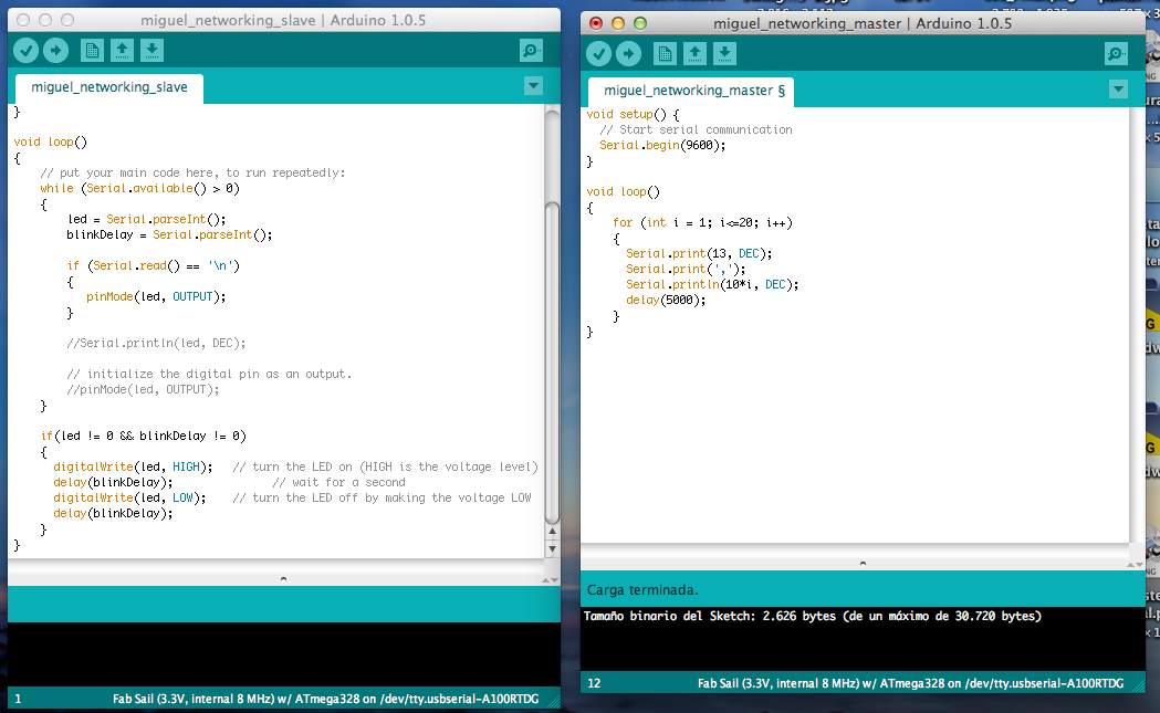
Here is a video of the blinking LED in the slave board. You will see the LED in the right board and in the right side of it.
What I learned
This assignment was more difficult as I thought; I expected to make a radio board and have a wireless protocol but I know I will have to work more on it to success. It is maybe not a about the soldering or the componnets, maybe is the design that I did it incorrectly. I did a check list and I could not find teh error; after Fab Academy I will find out where it was the mistake.
The master and slave protocol with the two wired boards went good, I learned how to program both in order to give them specific orders.
You can download all the files related to this week here.