ELECTRONICS DESIGN
Goals:
This week the goal is to redraw the echo hello-world board and adding at least two components to it: A LED and a button.
At the Lab:
The first thing that came to my mind after attending the lecture of Neil was the old times when I studied electronics at university. The lecture was great but as we know, electronics is full of concepts that are not so obvious and I had to refresh hard my memories from that time. I'm still in that process...
He gave us some very well detailed explanations of the components that we were going to use in the future assignments and told us where to find them in case of documentation.
Using Eagle:
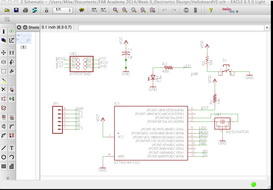
I am following Anna's tutorial because is just simple enough as importing the required fab and component libraries, and putting together a schematic that includes the hello-world board to add later on the additional switch and LED necessary.
The best way to accomplish the assignment is by designing the schematic and then the board layout in Eagle and finally creating a .png file from the traces to later on use the necessary milling software to create the board.
I follow Anna's layout to create the board and then route all the traces using 16mm. I test that the traces are not too close together because later on it will be a disaster. That is a very important step.
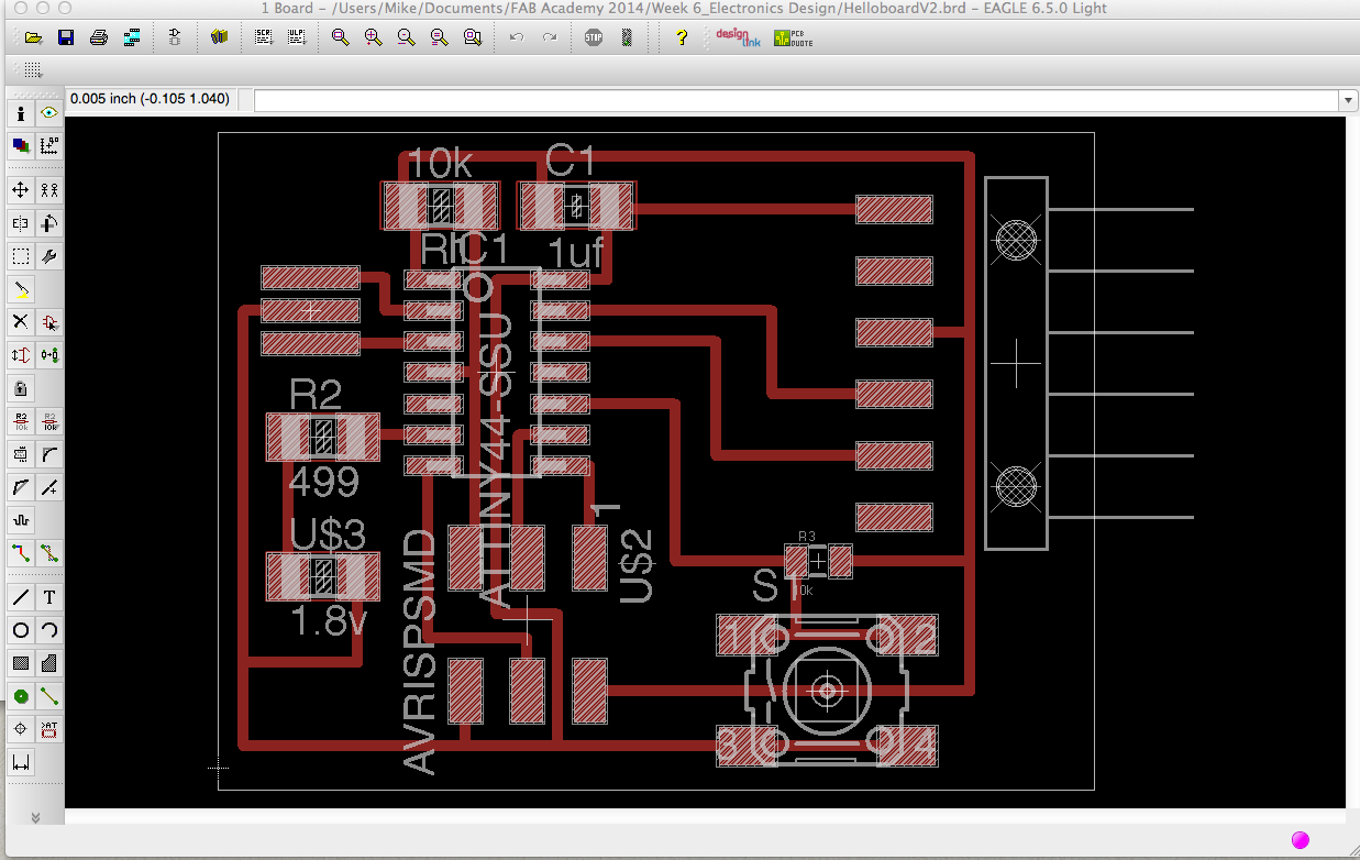
Once the traces are developed in the most compact area I can, I run the design rule check in Eagle to test that the circuit can work correctly. I receive some warnings (ie. Some unconnected wires) and after solving them I'm ready to make my .png file.
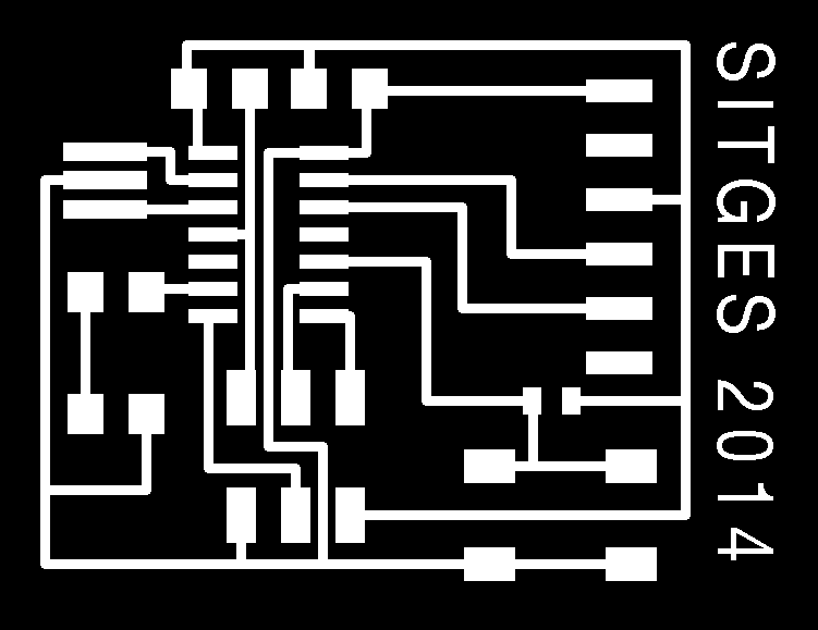
This is also very important: we have to create a white image with a black border in order to cut the board.
The .png file has to be send at 500dpi; monochrome from Eagle. After that I import both files, the board and the black border one to Fab Modules. With the help of Francisco and his experience on knowing the settings of the Modela and also by knowing what is black and what is white; we send the images to the machine.
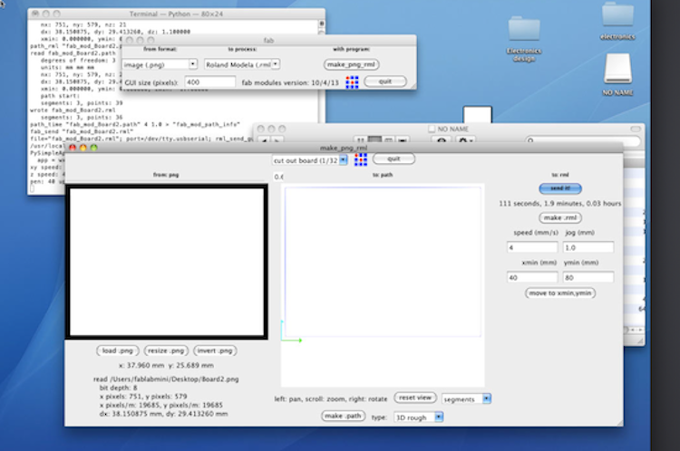
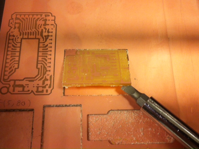
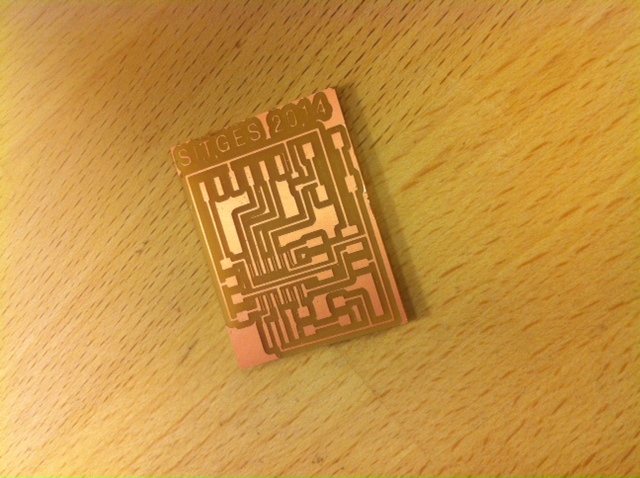
My first attempt works great; Thanks Francisco! I didn't calculate very well the black frame and I almost commit a fatal mistake by crashing the traces. But finally I am able to milling and cutting the board.
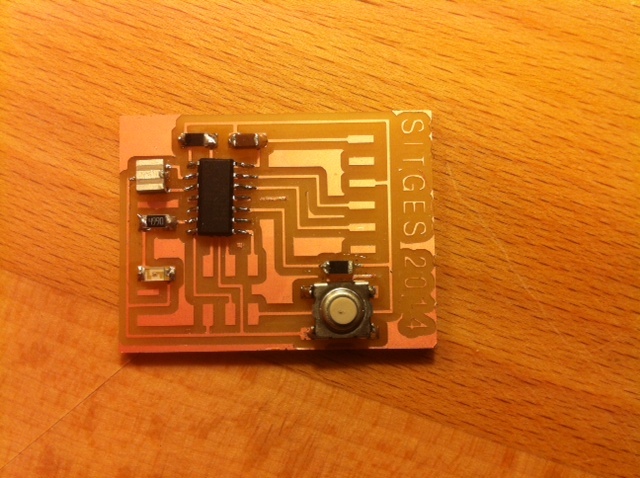
After that I just need to stuffing the board with all the componnets. Unfortunately I don't have time enough to finish it all but for the moment this what I have done so far. I'll try to stuff the pins during the weekend.
At the end:
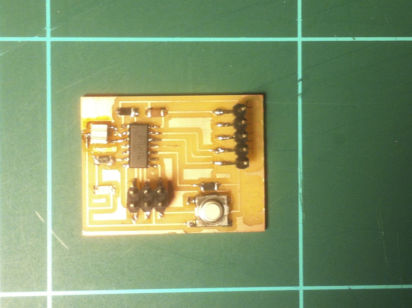
I came back to the lab during teh week and I could have some time to stuff the rest of the components needed. This is the final result:
Conclusion of what I learned:
Eagle is not such a friendly software as I thought in the beginning but is powerful enough to be one important tool for designing schematics and electronics boards.
I also had a very good luck with the bit because it did't break during milling my board but I've seen many bits broken because of reasons that I cannot explain. Probably because of a bad using but also probably because of their quality. I think we should always make an effort to have the most reliable components in the lab, even I know those are probably more expensive than others.
You can download all the files related to this week here