Assignment
· Read data sheet for ATtiny44a
·
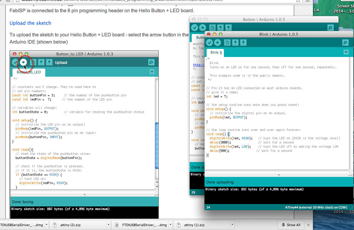
Using the Fab ISP (in-system programmer) programme the ATtiny44A microcontroller on your
Hello Button + LED board that we made during the Electronics Design week
How I got
started
I started by
checking out the data sheets on the ATtiny44 and made a copy
of the pin layout then got stuck into downloading software for
the Mac. This was a lengthy process but with attention to detail
and perseverance and with all downloads in place I was able to
get started with programming. The goal is programme the board
we made get a programme loaded onto the board and make small
changes to it to get used to programming. I made a start by
following the step by step tutorial Embedded Programming –
Arduino IDE first in Ubuntu then on the Mac. As my Fab ISP was
not responding I borrowed one ( thank you David) until I have
time to make another asap.
Hardware
The FAB ISP we made in class
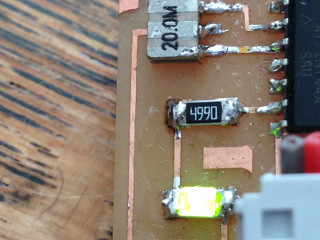
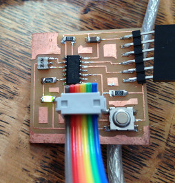
Hello button +led board
Ribbon cable
FTDI cable
Software
Checked FTDI driver installed
Download the Arduino IDE software
Download ATtiny board files
GCC and avrdude
Xcode
CrossPack-AVR
Check data sheet for useful info on the ATtiny44
My progress with programming so far
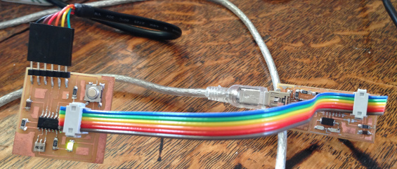
I connected the programmer to the ISP header on the
LED+Button board with an FTDI cable and then
configured it to run at 20MHz. I had problems with
Burning the Bootloader with errors at first. After
checking my set up I realised the FAB ISP and
hello board were not correctly connected and when this
was changed hey presto everything ran smoothly and I
was able to follow the tutorial on both the Mac and
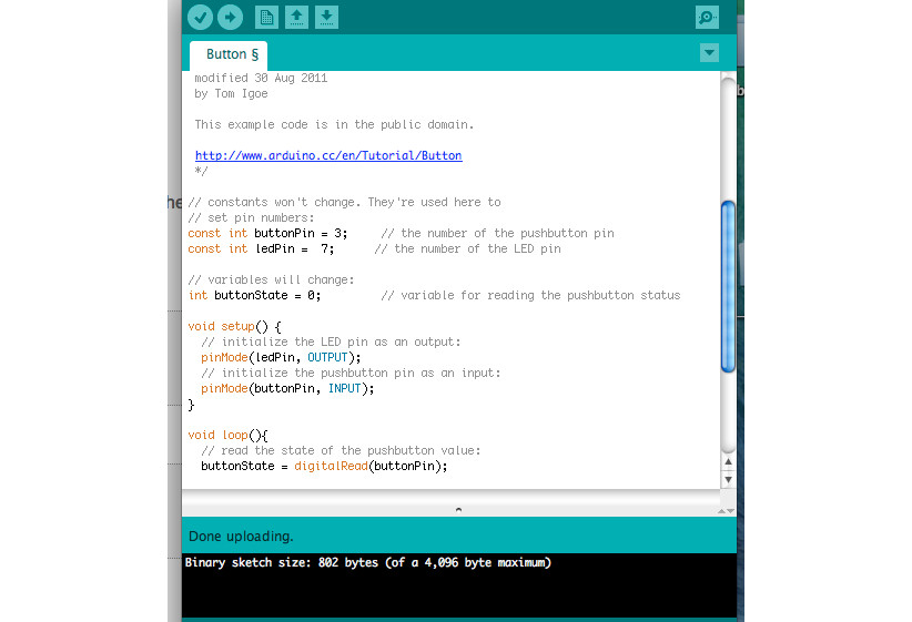
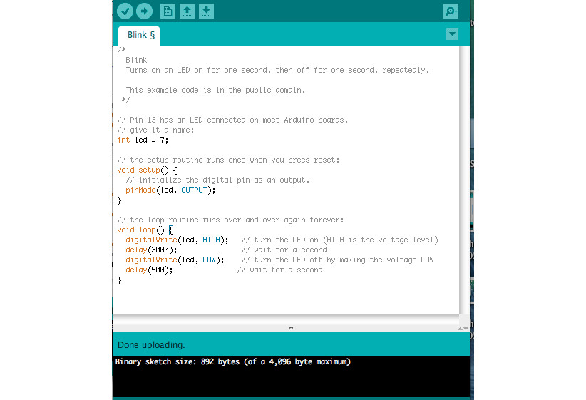
Ubuntu with no problems. I changed the pin numbers to
match up with those on my board. I spent some time
making small changes to the Button and Blink example
and got very excited about making the LED flash at
different speeds.

What next
Other useful info
ATtiny 44 / Arduino Pin-out numbering
|
ATtiny 44A Pin Number |
Corresponding Arduino Pin Number |
Details |
|
1 |
No
number no access |
VCC
(+) |
|
2 |
Pin
10 |
|
|
3 |
Pin 9 |
|
|
4 |
No
number, no access |
Reset |
|
5 |
Pin
8 |
PWM |
|
6 |
Pin
7 |
PWM,
Analog Input 7 |
|
7 |
Pin6 |
MOSI PWM Analog input
6 |
|
8 |
Pin
5 |
Analog
input 5, PWM MISO |
|
9 |
Pin
4 |
Analog
input 4 SCK |
|
10 |
Pin
3 |
Analog
input 3 |
|
11 |
Pin
2 |
Analog
input 2 |
|
12 |
Pin
1 |
Analog
input 1 |
|
13 |
Pin
0 |
Analog
input 0, AREF |
|
14 |
No
number no access |
GND
(-) |