Having no previous experience
of electronics I started by following the very helpful tutorial
and the cadsoft tutorials on how to use Eagle. Both were fairly
easy to follow but I did come across problems when I checked the
Design Rules and various errors came up so had to take much
appreciated advice on how to resolve these.
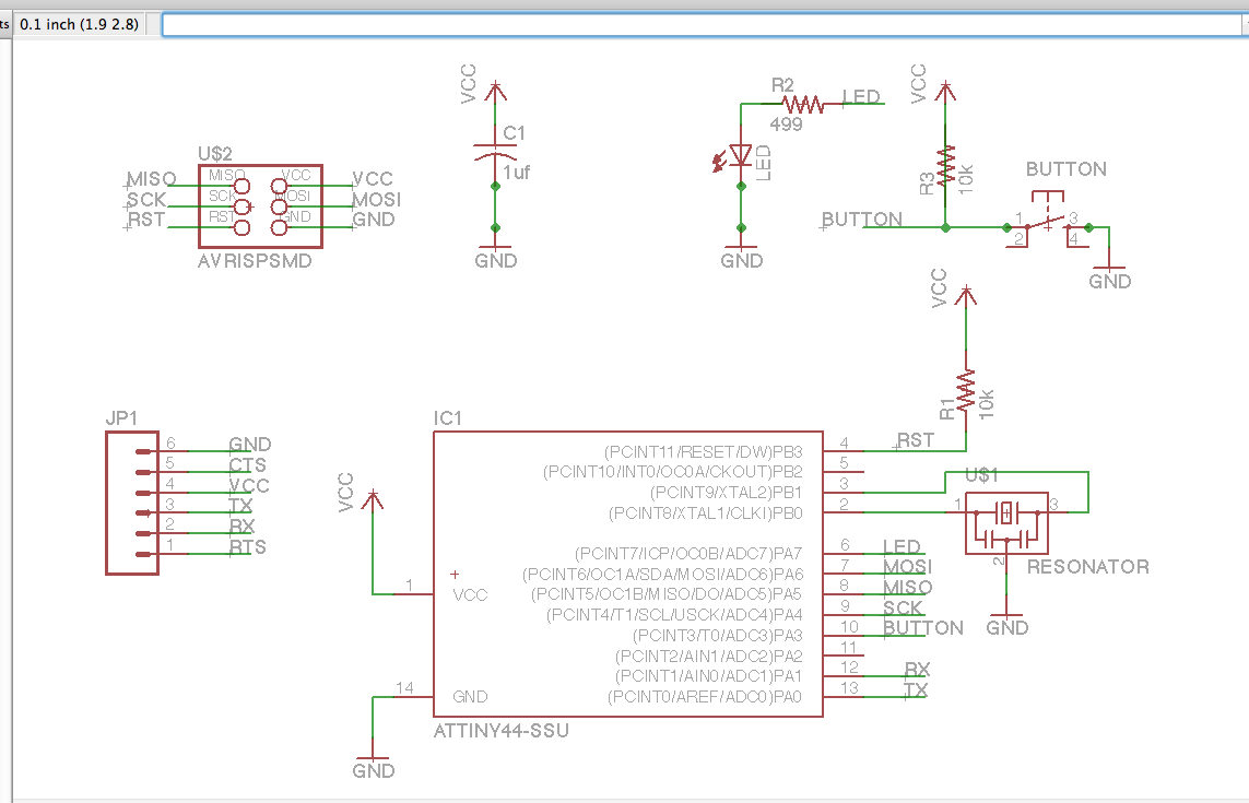
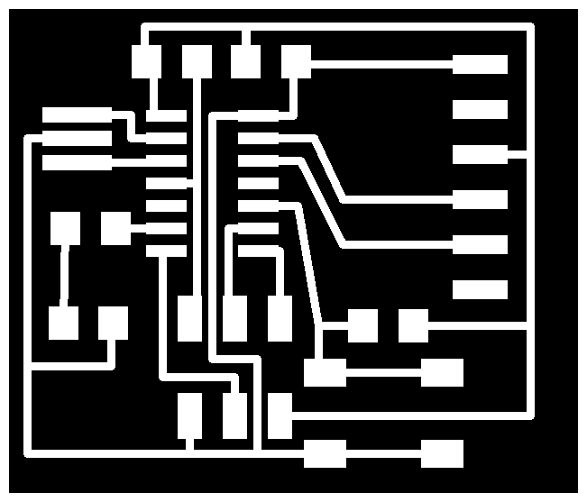
The
schematic and board are shown below


I then exported the .png files and opened Gimp to adjust sizing
and add a border.
Milling
using the Modela
Milling the board took some
time as I had to review how to set
x and y because the border for cutting the board was a
bit tight and the settings had to be exact so I got lots of
practice on the Modela which I'm sure will be very useful in the
weeks to come.
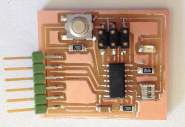
Stuffing
the board
I reviewed Neil’s class page
to help me identify and find all the parts to stuff the board, I
found this quite difficult and time consuming but with practice
I’m starting to get the hang of sifting through the detail for
helpful data eg which way round to place the switch and the led.
List
of parts to solder to board and what to consider when placing
on the board to solder
Attiny44A microcontroller
AVRISPSMD (AVRISP) 3 x 2
pin DIL header
Led (1206 mil a
thousandth of an inch size of LED) LED’s have
polarity the side with the line connects to ground
FTDI-Header powers the board -
6 x 1 single in line SIL header 0.1 inch standard size
space between pins
button OMERON 6mm switch
Capacitor 1206 - 4 pins on 2 sides see data
sheet to check layout on board
resistor 1206 x2 - value
of 10K
resistor value 499 OHMs
capacitor - value 1uf
20MHz resonator
Things learnt
I've learnt lots this week and still
loads more to learn!
· Give
myself more space when designing the board
· How
to identify most components
· More
confident with soldering now
· How
to use eagle to design boards

Files for my board design