My aims
Research
I had originally wanted
to make a robot but have become interested in robot faces,
expressions and communication so I thought I would take
inspiration from the wealth of art history in portrait painting
to help me explore the elements of facial expression and ways in
which a robotic face might communicate and how an audience might
interact with the face. I thought this would also provide me
with an interesting project to share with the students at school
and lots of opportunities to showcase the skills I’ve been
learning on the Fab Academy course.
Features of the project
Research links
Lego Mindstorms
"Adorable robots that teach kids to code" - Play-i Bo and
Yana uses programming languages Blocky scratch Java and Python
Code Club
Code Academy
Science Buddies
http://www.sciencebuddies.org
Adafruit learning systems - http://learn.adafruit.com
Cynthia Breazeal The rise of personal robots
Ted Talks – personal robots
ERWIN – emotional robots University of Lincoln

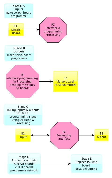
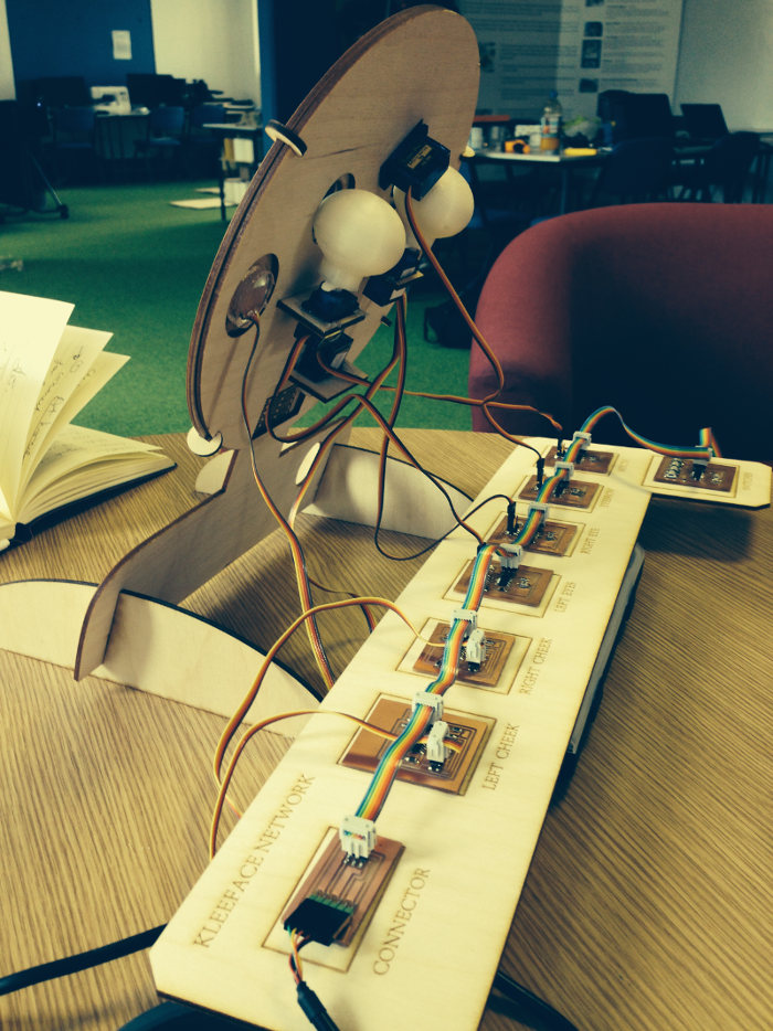
System Diagrams
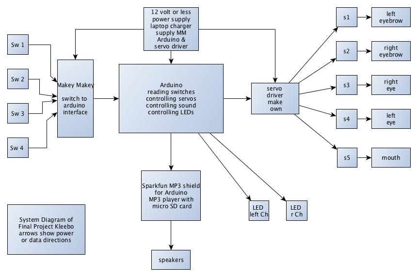
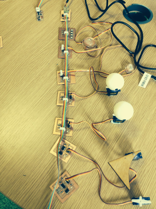
Network
A
complex system with simple individual nodes. I have chosen this
system to be scalable allowing the addition of other nodes
creating a modular system easier to debug and make as each part
can be made independently. Hopefully the network will be easier
to manufacture, change and mend.
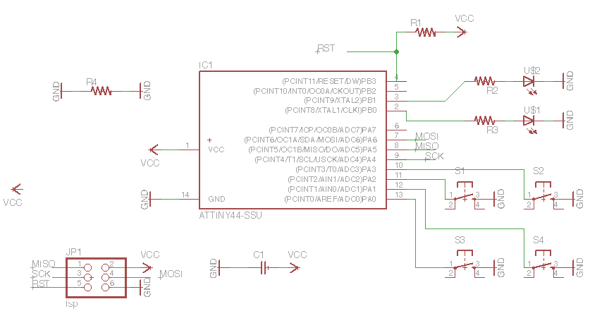
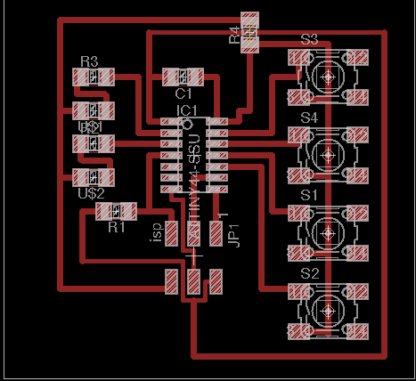
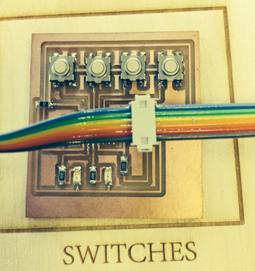
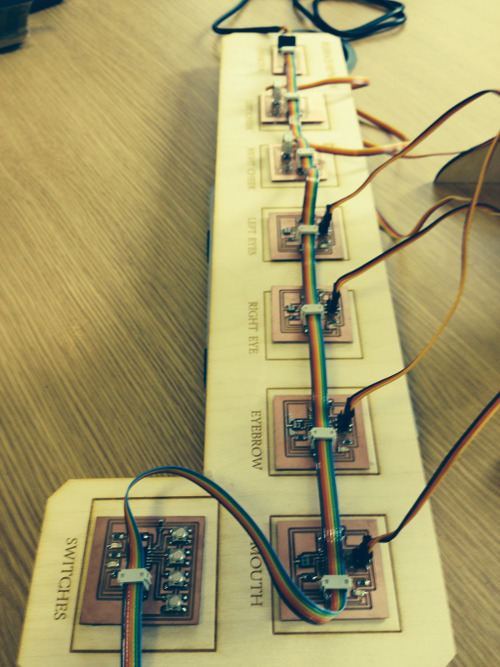
Board Designs
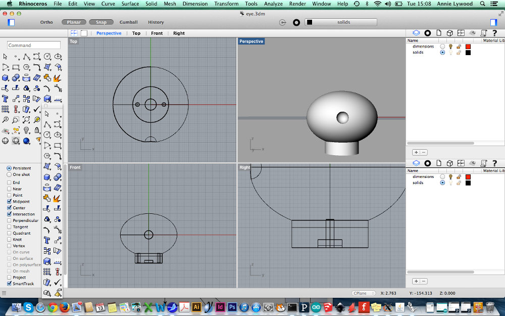
I
am making my boards using the Modella
|
Boards |
function
|
|||
|
B1 |
Switches board with 4 buttons to be
interface |
|||
|
B2 x 4 |
Servo board x 4 to move parts of
face – eyes,
mouth, eyebrows |
|||
|
B3 x 2 |
RGB LED board to light up cheeks |
|||
|
B4 x 2 |
Mini board for embedded LEDs |
|||
|
B5 |
Brain ATtiny 44 to replace computer and
make project stand alone |
|||
|
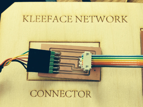
B6 |
FTDI connector with 2x3 header as bridge |
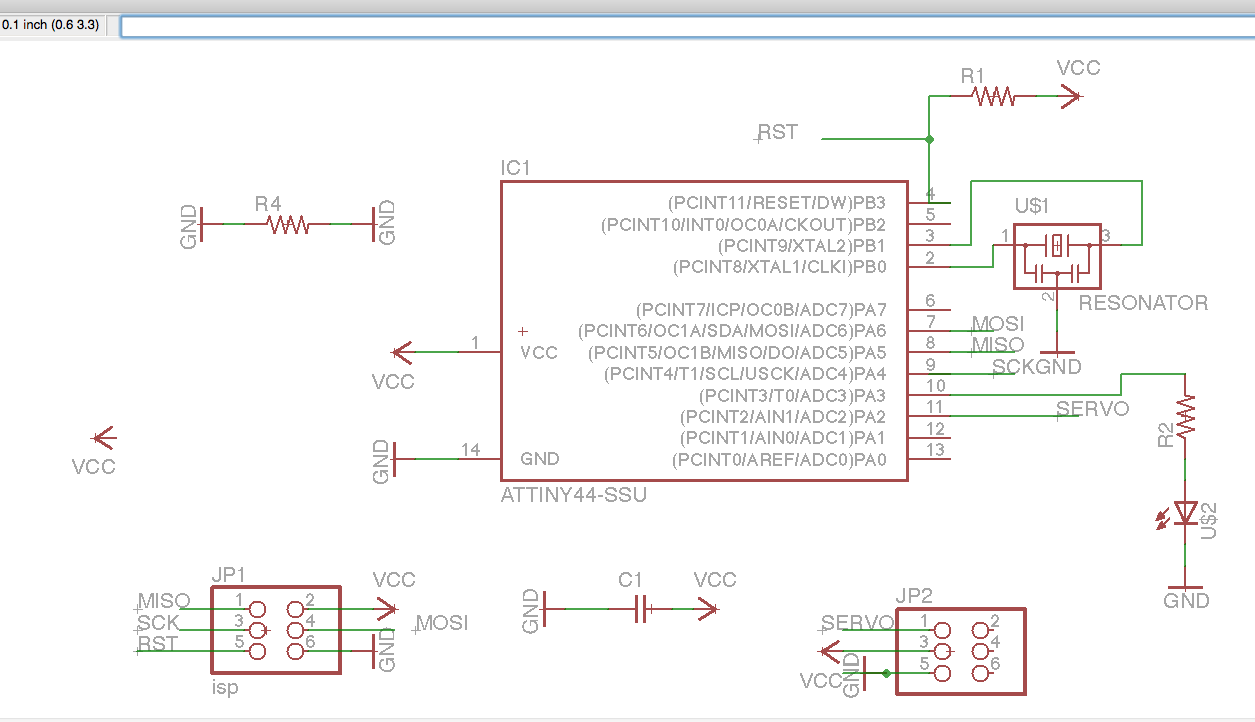
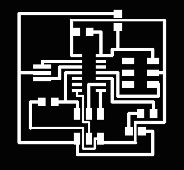
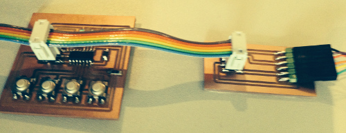
First
started by designing the servo board in Eagle, added LED, then
made, see below
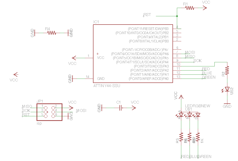
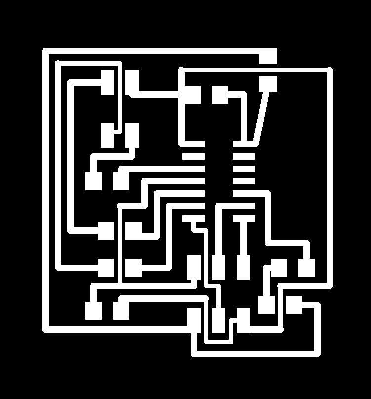
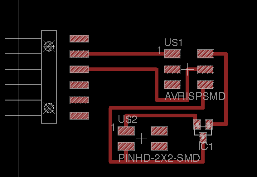
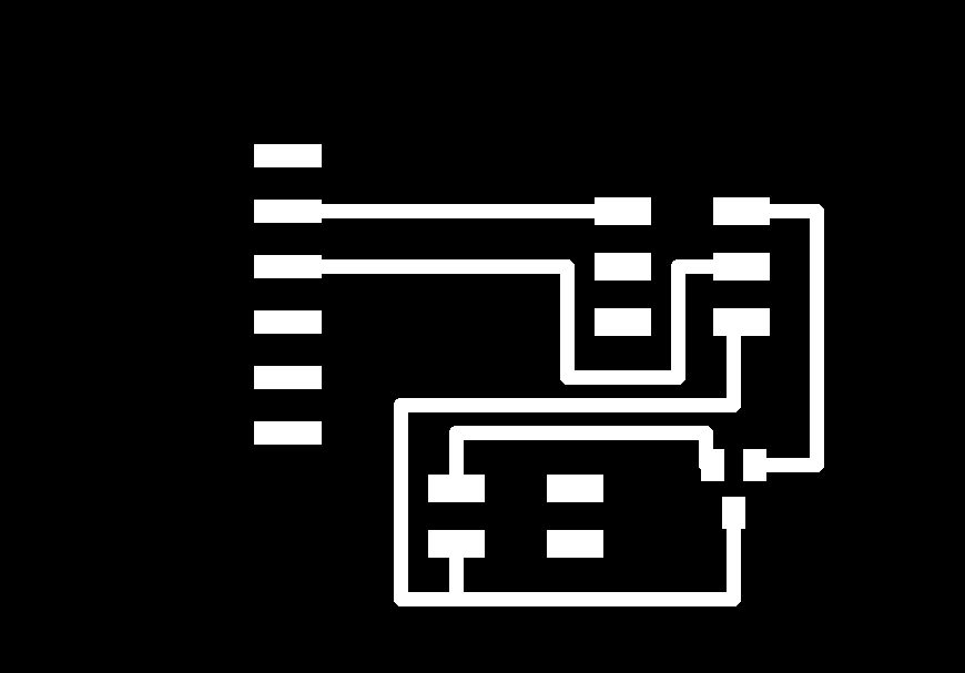
Servo Board
Servo Board - Schematic
Traces
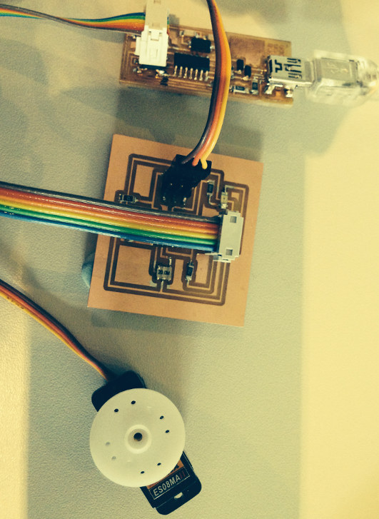
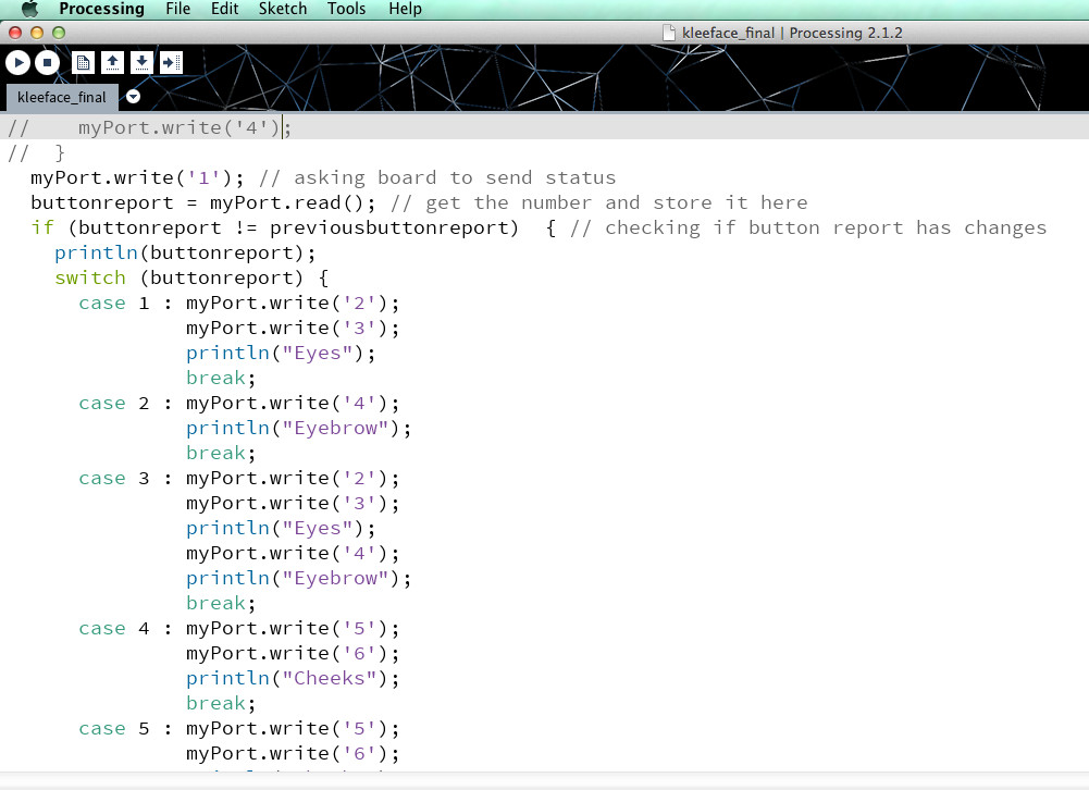
next
to programme in Arduino using my
FABISP - then to test the eye movement
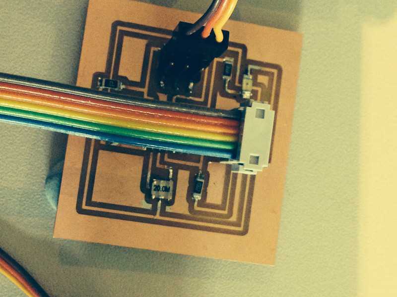
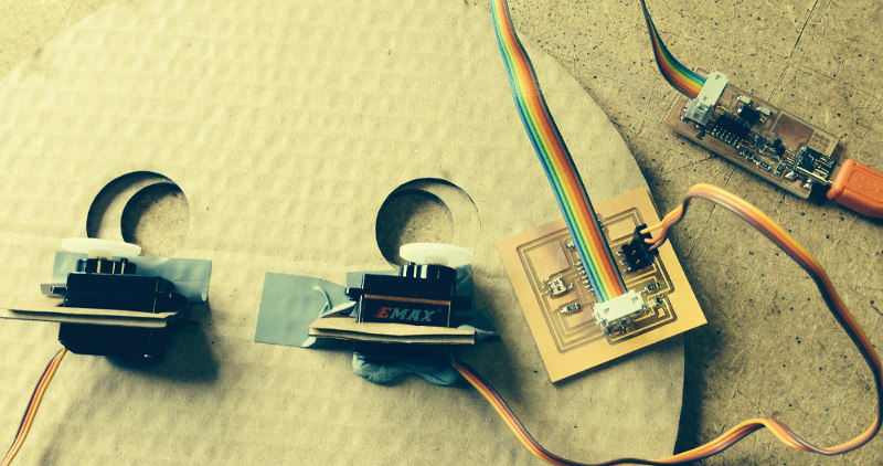
sketch showing working out RGB LED
connections with header below
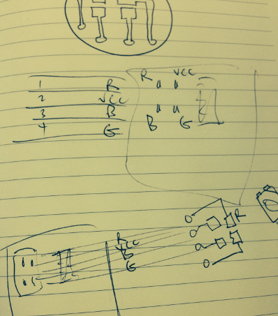
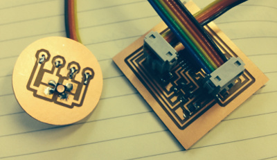
photo showing embedded LEDs working
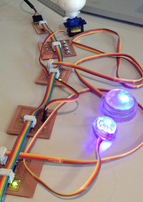
The network of
boards being programmed and tested below - all working, great!
I
will use Arduino IDE to programme my boards and Processing to
communicate via my computer to each board.
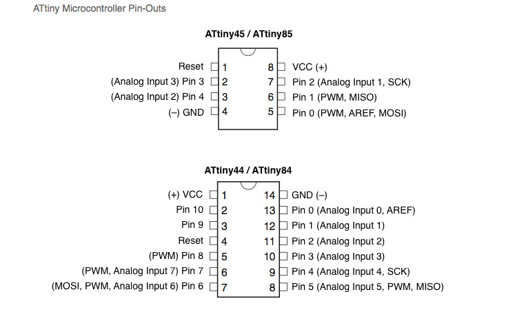
Useful
reference for programming ATtiny with Arduino Highlowtech.org/?p=1695
PLUS ATTINY PINOUTS BELOW
I used Binary numbers to workout the ID for the switches and
boards
Binary numbers to 15
|
0 |
0 |
0 |
0 |
0 |
|
0 |
0 |
0 |
1 |
1 |
|
0 |
0 |
1 |
0 |
2 |
|
0 |
0 |
1 |
1 |
3 |
|
0 |
1 |
0 |
0 |
4 |
|
0 |
1 |
0 |
1 |
5 |
|
0 |
1 |
1 |
0 |
6 |
|
0 |
1 |
1 |
1 |
7 |
|
1 |
0 |
0 |
0 |
8 |
|
1 |
0 |
0 |
1 |
9 |
|
1 |
0 |
1 |
0 |
10 |
|
1 |
0 |
1 |
1 |
11 |
|
1 |
1 |
0 |
0 |
12 |
|
1 |
1 |
0 |
1 |
13 |
| 1 |
1 |
1 |
0 |
14 |
|
1 |
1 |
1 |
1 |
15 |
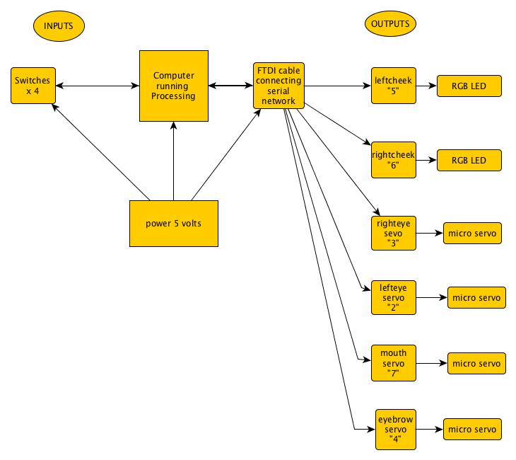
|
BOARDS |
ID from
Processing |
|
Kleeface_left_eye |
“2” |
|
Kleeface_right_eye |
“3” |
|
Kleeface_right_cheek |
“6” |
|
Kleeface_left_cheek |
“5” |
|
Kleeface_eyebrow |
“4” |
|
Kleeface_mouth |
“7”
|
|
Switches |
1”
|
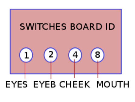
Commands Processing is sending out based on button
status. There are 15 possible combinations (see below)
|
BUTTON
NUMBER |
NAME
|
ID
of board sent from Processing |
|
1 |
EYES |
“2”
&”3” |
|
2 |
EYEBROW |
“4” |
|
3 |
EYES
&EYEBROW |
“2”
“3” “4” |
|
4 |
CHEEKS |
“5”
“6” |
|
5 |
CHEEKS
& EYES |
“2”
“3” “5” “6” |
|
6 |
CHEEKS & EYEBROW |
“5”
“6” “4” |
|
7 |
EYES
& EYEBROW & CHEEKS |
“2”
“3” “4” “5” “6” |
|
8 |
MOUTH |
“7” |
|
9 |
MOUTH
& EYE |
“2”
“3” “7” |
|
10 |
EYEBROW
& MOUTH |
“2”
“8” |
|
11 |
MOUTH
EYEBROW EYES |
“8”
“2” “1” |
|
12 |
MOUTH
CHEEKS |
“5”
“6” “7” |
|
13 |
MOUTH
CHEEKS EYES |
“7”
“5” “6” “2”
“3” |
|
14 |
MOUTH
CHEEKS EYEBROW |
“7”
“5” “6” “4” |
|
15 |
MOUTH
CHEEKS EYEBROW EYES |
“2”
“3” “4” “5” “6” “7” |
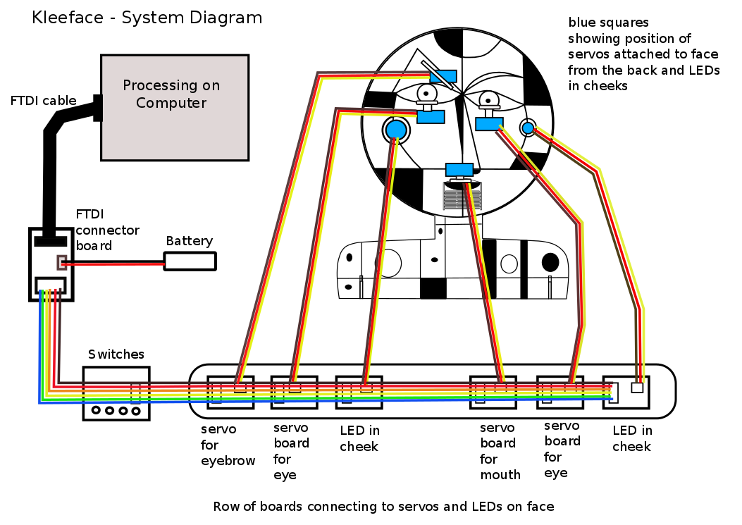
| Kleeface_leftcheek_5 | as right cheek / they work
together
|
| Kleeface_switches_1 | switches |
| Kleeface_rightcheek_6 | leftcheek |
| Kleeface_LEservo-2
|
lefteye |
| Kleeface_REservo_3 | rEye3 |
| Kleeface_mouth_7 | mouth
arduino |
| Kleeface_eyebrow_4 | eyebrow_arduino |
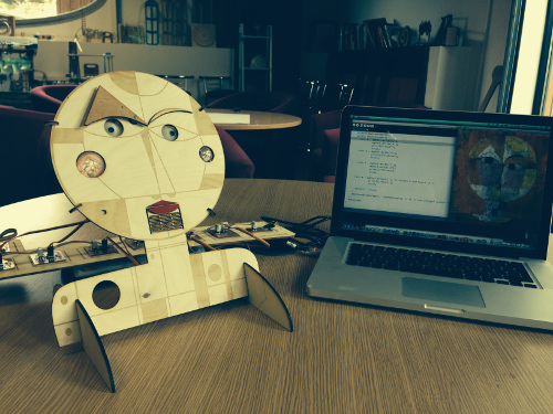
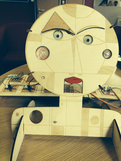
I
need to work out how to move the various parts of the face,
eyes, mouth, and eyebrows, using the servos. To achieve this I
have first to make a prototype face, 3D print the eyes,
think how to attach and position the servos, design and make my
own servo board so that I can test the movement of the eyes and
mouth.
Problems to solve
· Work out
flexures to move the mouth
· Work out pivot
points for eyebrows and servos
Work out position of eyes and servos
· In Rhino redraw
the back plate of face, position all the press-fit connectors to
hold servos so front and back of face match up
Useful website for
understanding how to use servos
http://www.societyofrobots.com/actuators_servos.shtml
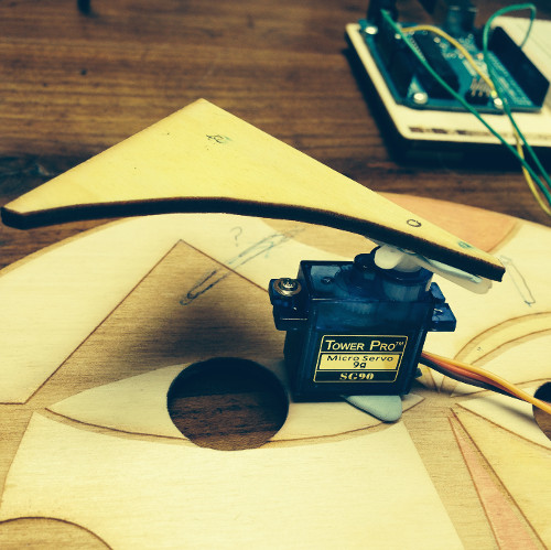
Positioning the 4 servos on face, next to think how to
attach them and test - testing movement
and position of eyebrow
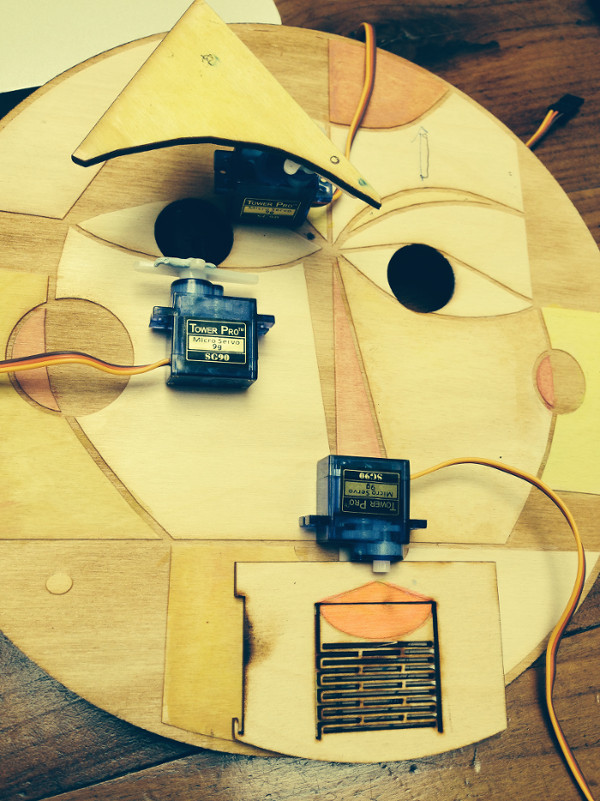
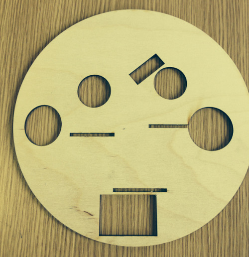
Fabrication
What needs to be designed and made?
|
Parts to be made |
Process used and decisions to be made |
|
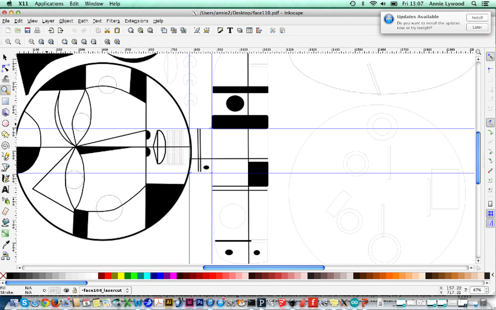
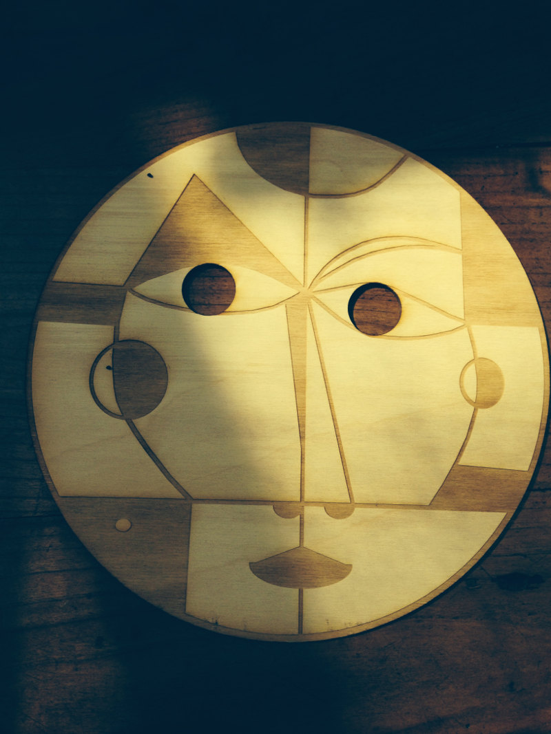
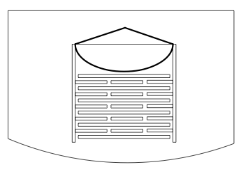
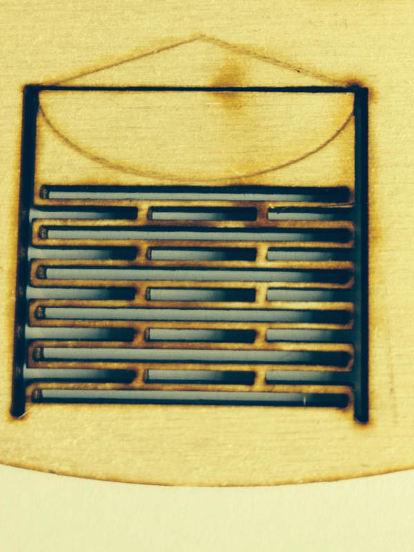
Face |
Lasercut with final changes to design
adding flexure to move mouth, cutout areas for cheeks to
be embedded Pivot points for servos, cut grove for arch
of servo for eyebrow |
|
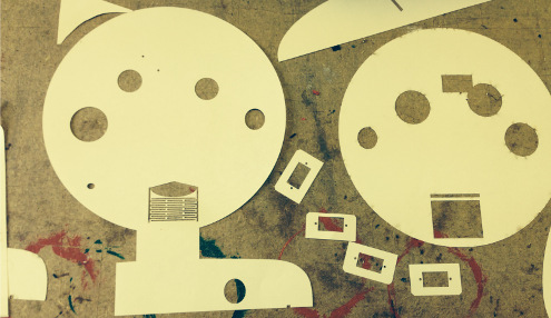
Pressfit structure to hold face so able to
sit on the table |
Lasercut and decide on final design and
size, position of servos and pressfit connectors |
|
Pressfit connectors to hold servos |
Lasercut – finalise size and position on
face Test press fit connectors to check it will
hold servos |
|
Eyes |
3d print in white with pupil – improvements
to existing shape – check size |
|
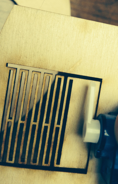
Eyebrows |
Lasercut, decide on movement, pivot point,
and how to connect them to the face, how to connect
eyebrows to servos and arc of movement |
|
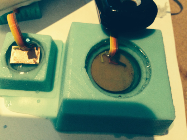
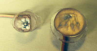
Cheeks |
Draw up in Rhino – cutout mold on shopbot –
use epoxy resin to embed LED on mini board to allow for
connecting |
|
Mouth |
Laser cut mouth and think how to attach Flexure and servo to move mouth, where to
place servo? Consider pivot point |
Started
with 3D print of eyes having drawn up design in Rhino to
appropriate dimensions
Attached
eyes
to servos to see how they fit on the face, is the shape
right? Printed in black as our only option so then needed to
source other colours and consider how to achieve a better
quality finish
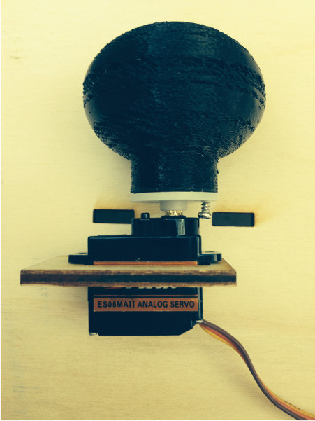
First prototype of eyes
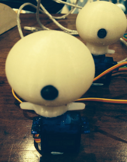
Second prototype of eyes,
resized and in white
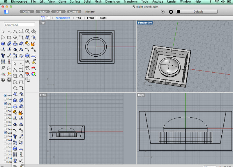
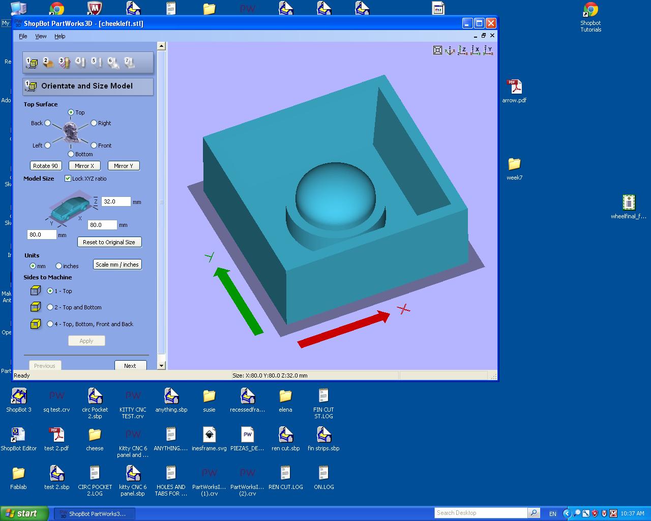
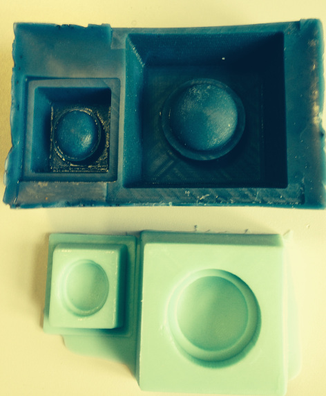
Molds
for cheeks and embedded LEDs
Started
with drawing cheeks in Rhino using measurements from the face
and then cut out the mold using the Shopbot. This all went very
smoothly.
Backplate
for face
Thought
of simple ways to connect the servos so they are secure and
don’t interfere with the design of the face. My concern at the
moment is that they will be heavy so stability of the structure
is paramount. My solution at the moment is to add a back plate
to the face which all the servos and linkages can be attached
using pressfit connectors. This has required lots of
testing to get all the parts and lasercuts in place. I found
drawing up the back plate in Rhino more accurate and easier to
measure than Inkscape.
Future Plans for Kleeboo
Files
for final Project
Fabrication
stl file left
cheek Rhino
stl file right
cheek Rhino
files 3D printing
eye Rhino
files pdf face inkscape
for laser cutting
Programming files
Arduino IDE
programs
eyebrow servo
programs eye
servo
programs
mouth servo
program RGB
LED cheek
program RGB
cheek
Processing
processing
Eagle
files for Boards
Servos
eagle files
servosch
RGB
LED
FTDI Connector
FTDI connector sch
FTDI
connector brd