Final Project - Augmented Rubik's twist
FabAcademy class 2014
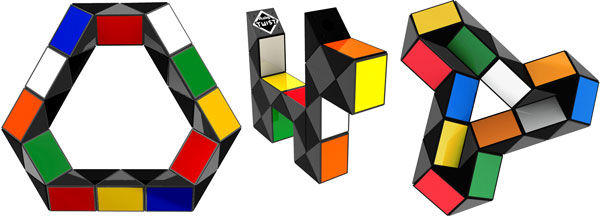 For the final project I am attempting to build a digitally-augmented favourite toy of my childhood - Rubik's twist. Every junction of the puzzle needs to be able to measure and communicate it's position to an external device. The design of the junction is the biggest challenge in this project. It has to be mechanically sound to be able to maintain the shape of the puzzle, it should deliver a satisfactory haptic sensation of a click when the puzzle is twisted, it has to act as a measuring device and as a slip ring to pass the data about other junctions.
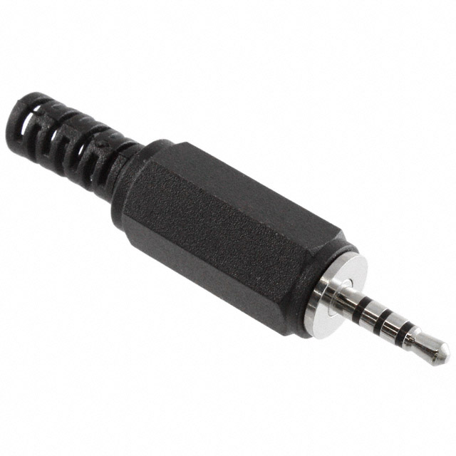 In one of the practical robotics books I came across a trick that audio jacks could be used as sliprings. 4-pole 2.5 mm audio jacks gives me the ability to send the power line and two data lines between the modules. Placing an ATTiny44 into each module, gives me the ability to measure the module's position and to send it outside.
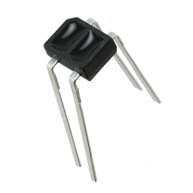
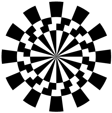 Position measurement will be done using two IR sensors QRE1113 on one face of the module and a patterned disc on the other face.

 A slightly modified version of the APA boards will be used, with only two APA ports, and an external board for the IR sensors.
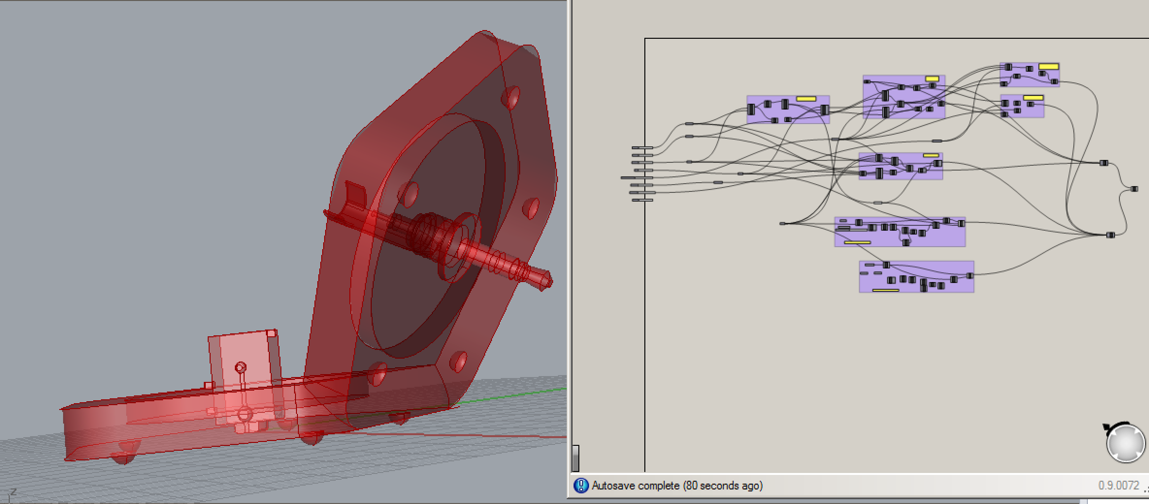 A completely parametric model was developed in Grasshopper, which will allow for quick adjustments during the physical prototyping stage.
milling the pcb's:
mistakes:
- outline traces were not inverted.result - screwed up pcb
- milling bit wasn't fixed properly due to a slipped screw in the rotor. result - broken bit.
- traces too close to each other - back to editing.
- pushing against the green table screw and table edge works quite ok as a reference position for milling the outline
- attaching duct tape to the bottom of the copper plate to compensate for unevenness of the table and improve adhesion
- mistake in eagle component for the 4-pin minijack. Mixed pin and switch in the schematics
A completely parametric model was developed in Grasshopper, which will allow for quick adjustments during the physical prototyping stage.
milling the pcb's:
mistakes:
- outline traces were not inverted.result - screwed up pcb
- milling bit wasn't fixed properly due to a slipped screw in the rotor. result - broken bit.
- traces too close to each other - back to editing.
- pushing against the green table screw and table edge works quite ok as a reference position for milling the outline
- attaching duct tape to the bottom of the copper plate to compensate for unevenness of the table and improve adhesion
- mistake in eagle component for the 4-pin minijack. Mixed pin and switch in the schematics
