| Week19 | Project Presentation |


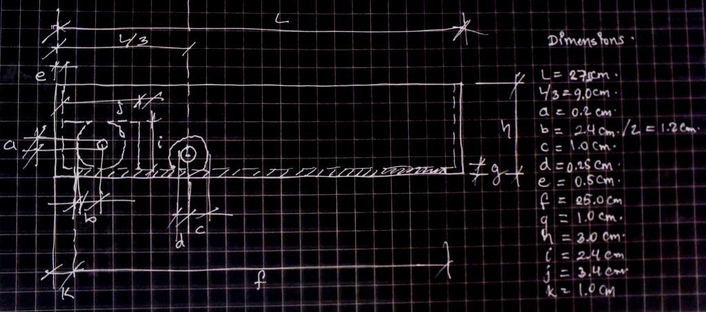 | 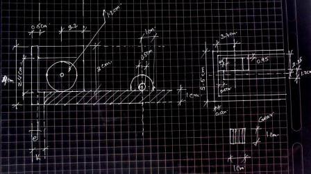 |
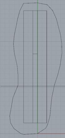
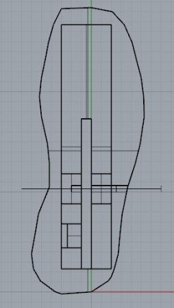
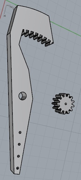
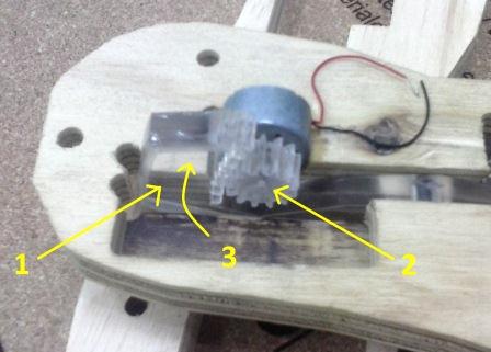
| platform's lengths sketch | Generator position sketch |
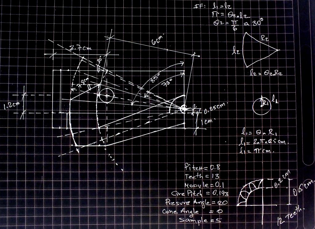 | 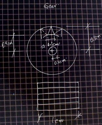 |
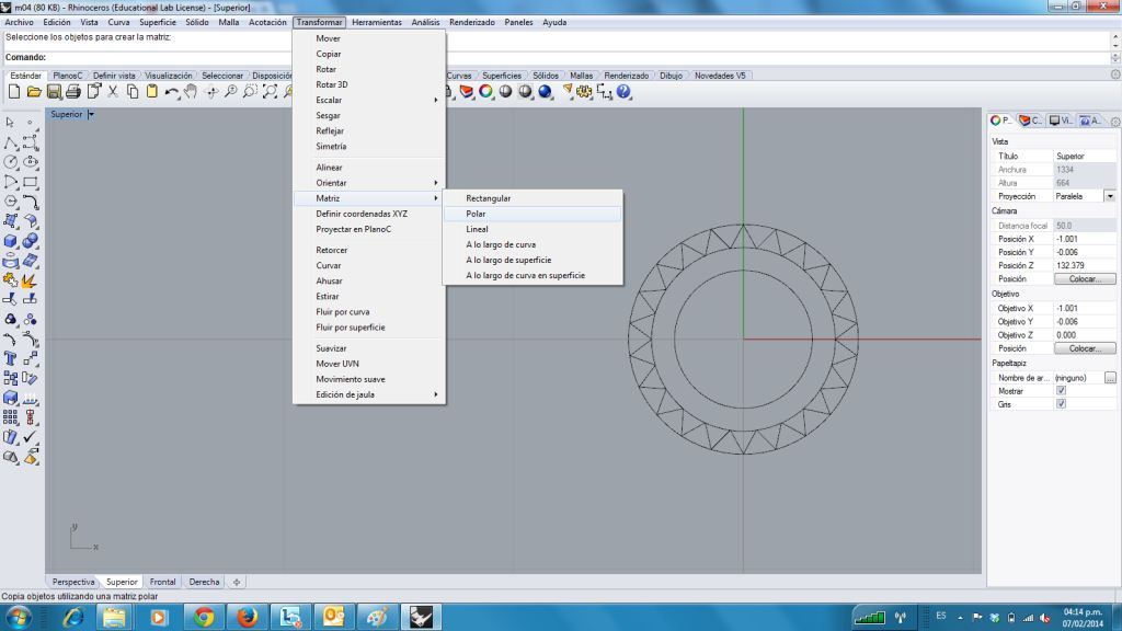
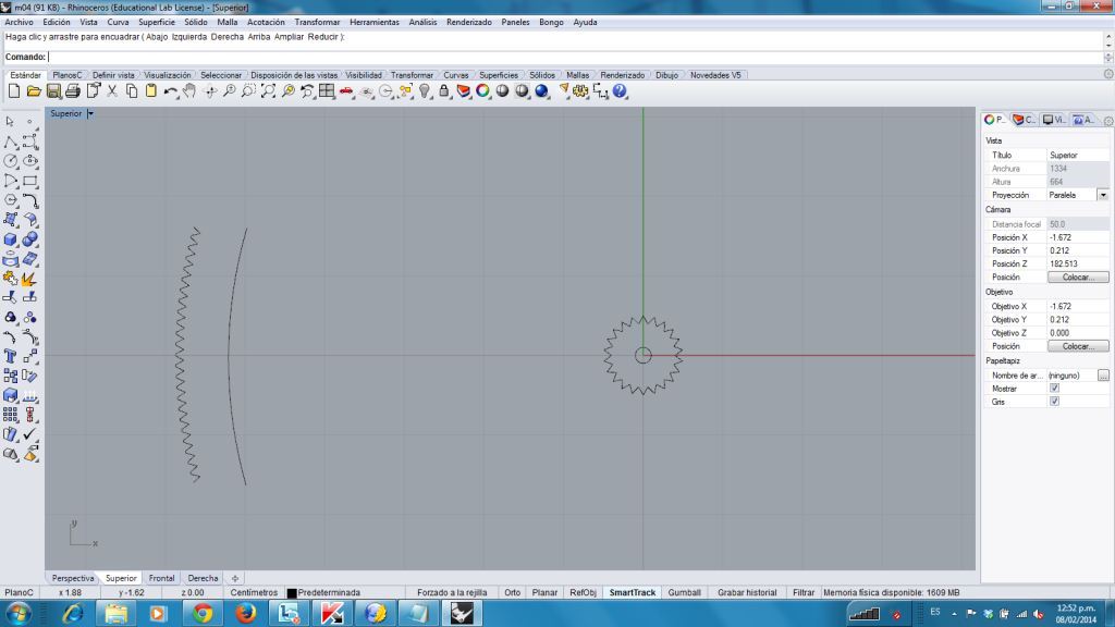
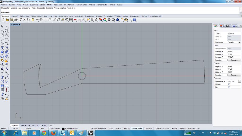
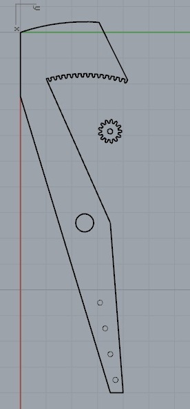
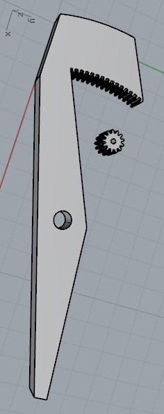
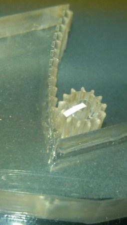
| lever's length sketch | gear size |
 |
 |
 |
 |
 |
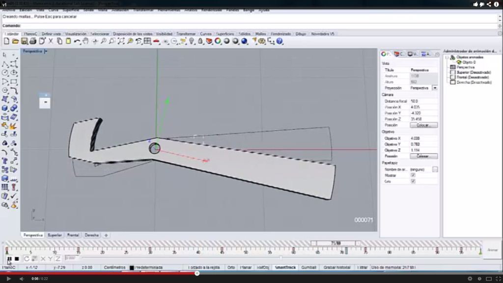 | 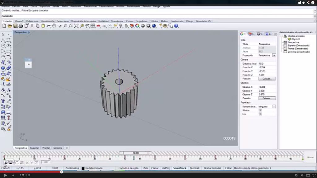 | 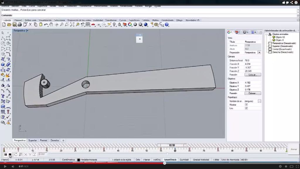 |
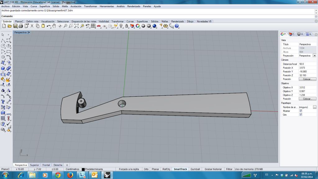
| Animation of lever | Animation of gear | Animation of lever and gear |
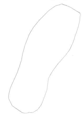
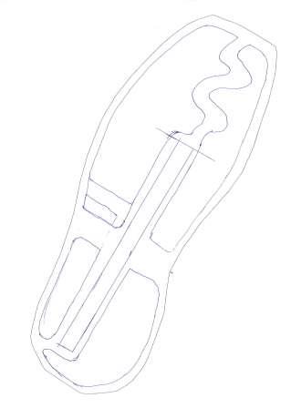
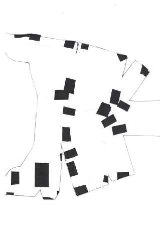
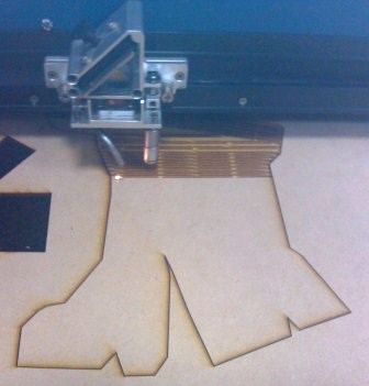
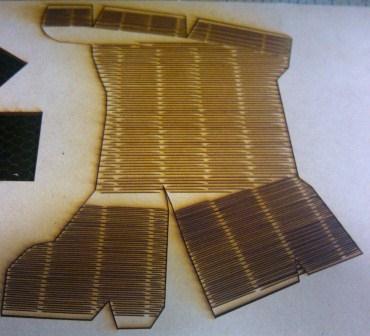
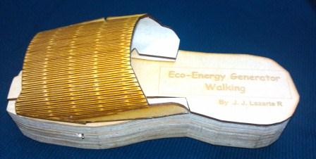
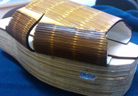
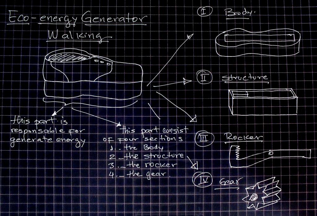
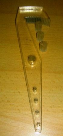
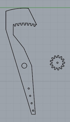
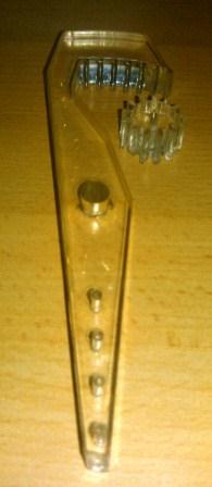
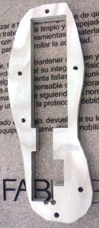
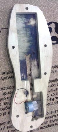
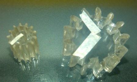
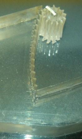
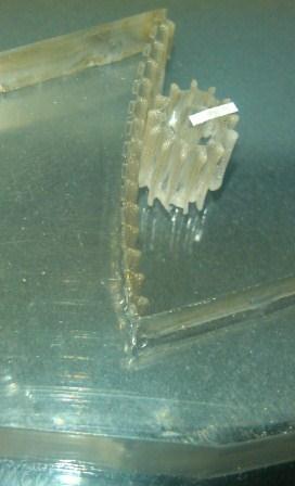
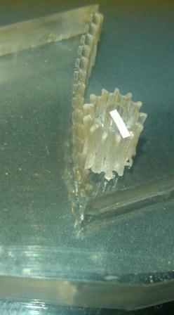
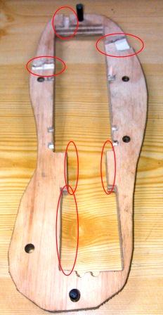
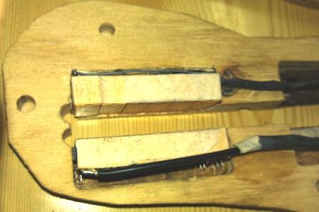
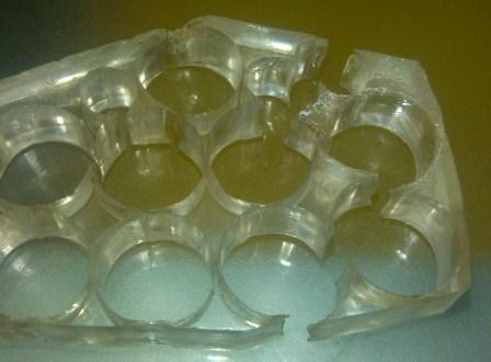
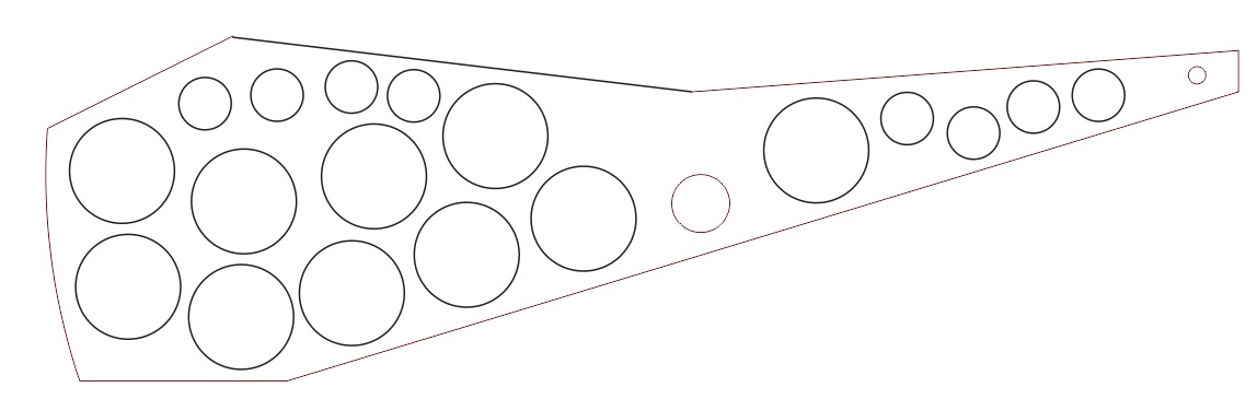
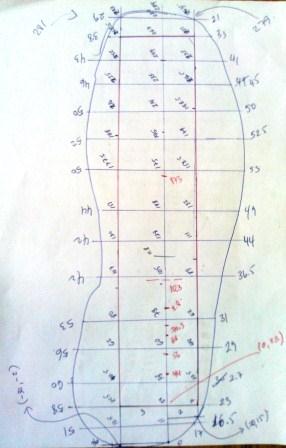 In the image shown is the template from which the data were taken ... | 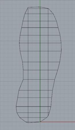 ...to draw the template model using Rhinoceros software. | 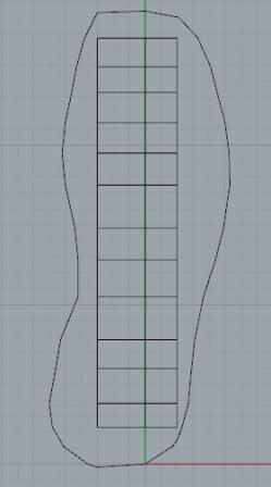 | 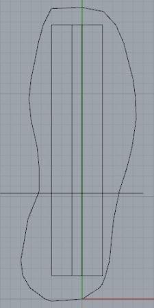 |
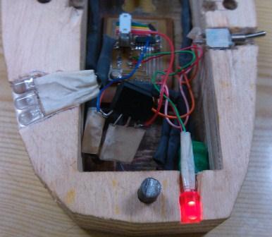
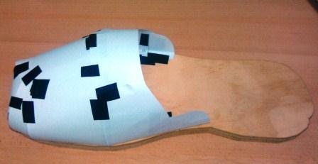
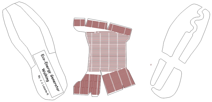
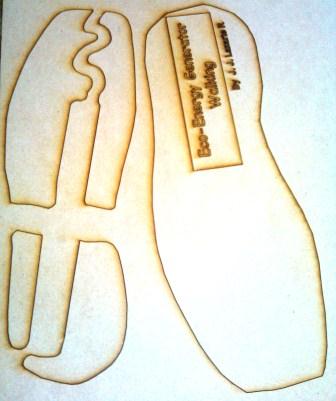
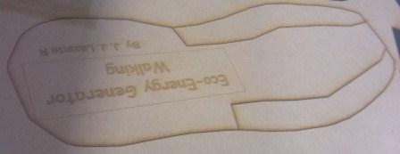
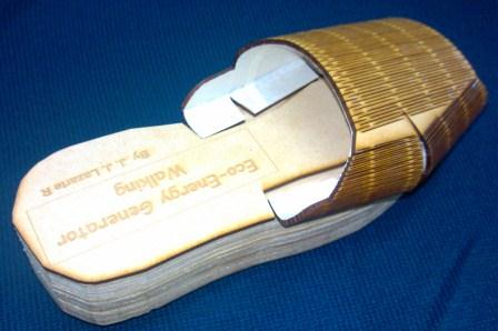
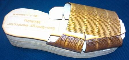
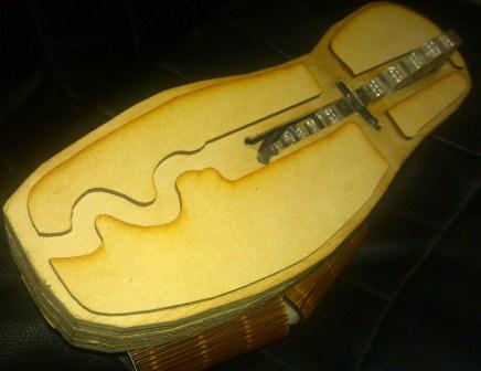
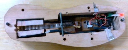
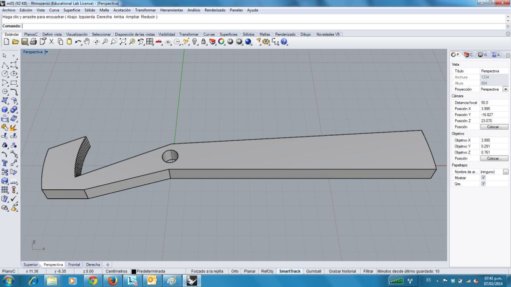
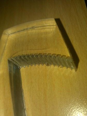
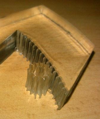
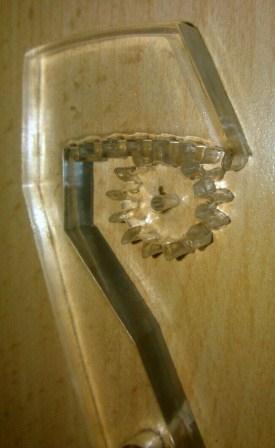
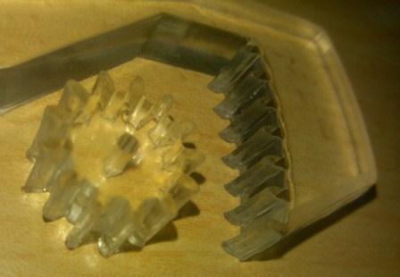
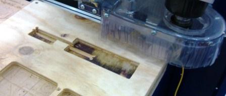
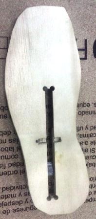
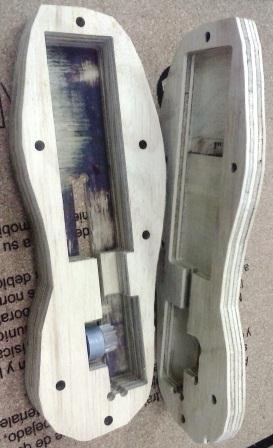
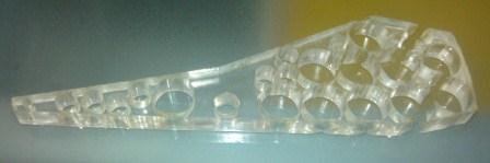
 |  |  Bottom where the lever shaft, generator and lever slot will fit... | 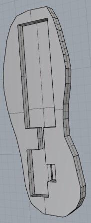 Top that will contain support for the foot |
 |  |  |  |
 |  |  |  |
 |  |
 |  |

 |  |
 |  |
 |  |
 |  |  |
 |  |
 |  |