Assignment Complete your final project, tracking your progress: What tasks have been completed, and what tasks remain? According with what was planned I have completed 3/4 of it. The tasks to be completed are: - Design and construction of the platform. (Completed) - Design and construction of the lever (Completed) - Design and manufacture of electronic circuits (in progress) - Design and construction support for the foot(in progress)
what has worked? what hasn't? About the parts that I have alredy done, all parts are working pretty well. I refer to:
- Design and construction of the platform. - Design and construction of the lever I´m
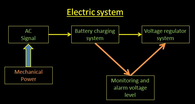
working in the electronics parts, making the design of the rectifier,
and the regulator, to transform the AC electric energy into DC
electric energy and so to charge a battery. After that, I must use a linear
regulator to obtain approximately 5V DC. In this part I will add an
intelligent system based in a microcontroller that monitors them the
level of the voltage charge and turn on to signal that charging has
been completed.
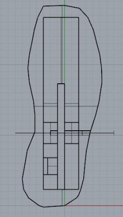
The last part that I need to define is the construction of the support for the foot. I propose a referential structure, but it needs improvement.
what questions need to be resolved? The questions that need to be resolved are:
- How to make the shoes more confortable for the user? - What materials will be used? - What shape will it have? - How will be the design of the monitoring and alarm voltage level? what will happen when? The posible answers of these questions are: - For to make more confortable the shoe I´m thinking to change the shape of the support of the foot. - About the material, I have two options, one is use leather and the other is use cloth. - About the shape, I want to cut the heel, because this made the shoes more confortable spite of the rigid platform. - For the design
of the monitoring and alarm voltage level, I think to implement it using
a micro controller that has the possibility to take the level of the
voltage and using a program activate an alarm which can be a LED
indicator. what have you learned? During
the proces of design and construct the differents parts of my proyect, I
learn about mechanic design, using tools of software, I learn to use
programs like Rhinoceros y develope whit it 2D and 3D estrucutures.
Which was something really new for me. How to work using microcontrollers of ATtiny family for input and output signals. And I learn to use the differents machines for milling and printing 3D structures.
documentation during development demand- vs supply-side time management spiral development.
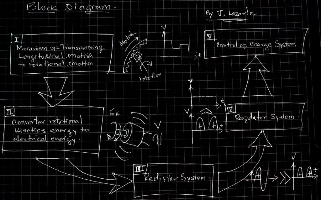
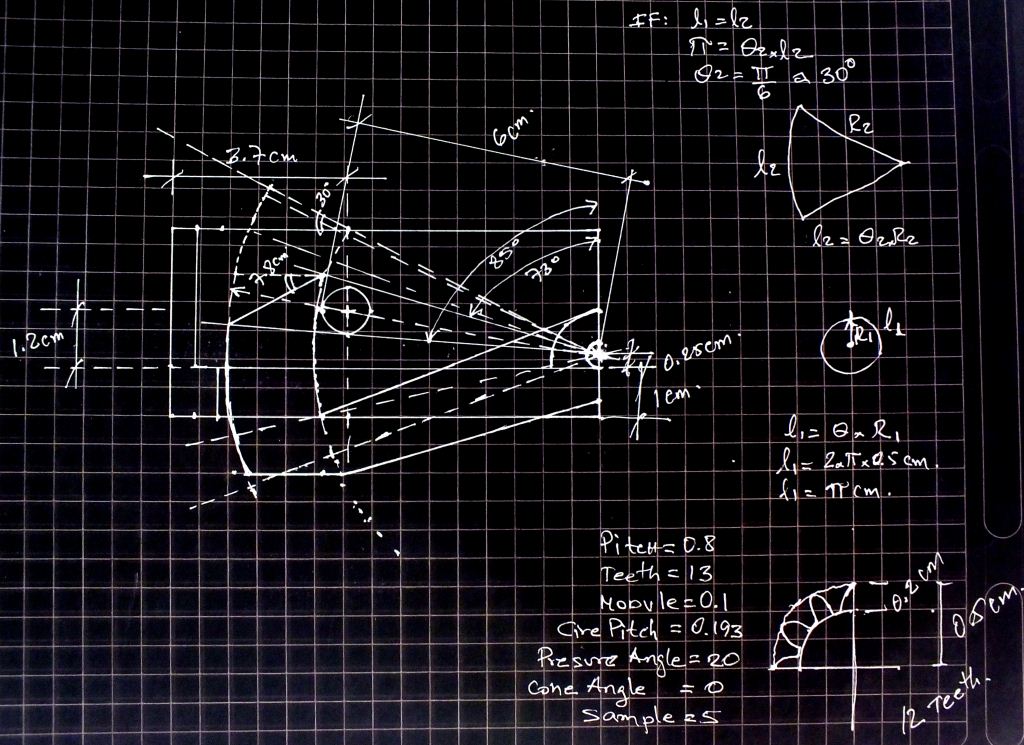
I start my proyect using the secuence shown in the next diagram.
Acording
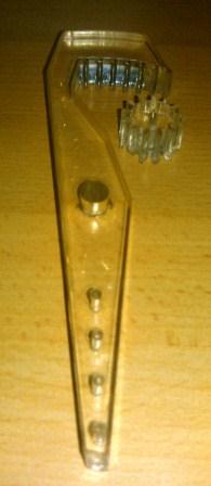
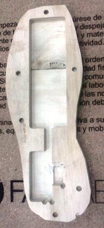
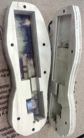
with this, the first part consists in to design the mechanical
structure, this consists of three parts, the lever, the gear and the
holder. This process is shown in the following figures.
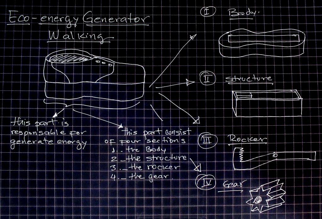
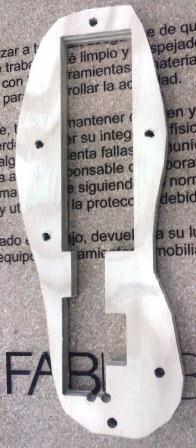
The
first figure shows the concept under which I start the mechanical
design, find the right dimentions of the three parts fit into the
size of a foot of an average size.
The right dimentions are showed in the sketch above.
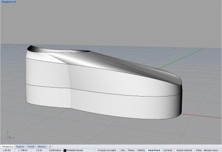
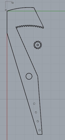
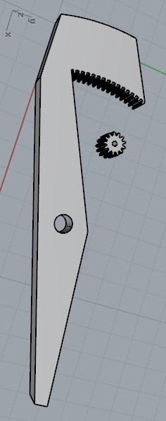
Using the software Rhinoceros I made the three parts an do after that I construct it using the machine shopBot.
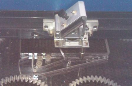
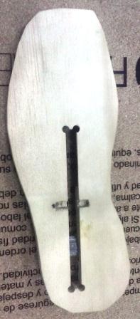
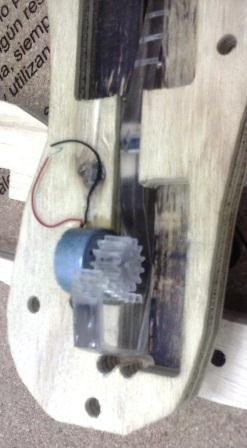
After
this, I start to assembling of the AC generator on the platform,
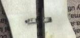
in that case i must cut a small piece of metal for use it like an
axis and hold it in the platform.
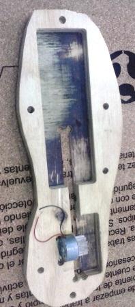
The
result of this is that now I can assemble not only the AC generator if
not also the lever and the gear. I show this in the following image.
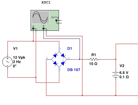
At this part I have the AC generator assembled, now I show how the first circuit transforms the AC signal in pulsed signal. When
the lever go up and go down it move the gear in one directión and in the
opposite direction, the result of that is that we have and AC
generator. The walking speed of a human
being is about 4Km/h, that means that we make 1.1m/s. and we need
to do two steps in one second, so we generate and AC signal of 2Hz
about. That is why I use and AC signal generator when I test my
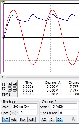
circuits. Now this is the rectifier circuit, and the signal of output AC generator and rectifier.
Blue signal is output of rectifier, and red signal in the input.
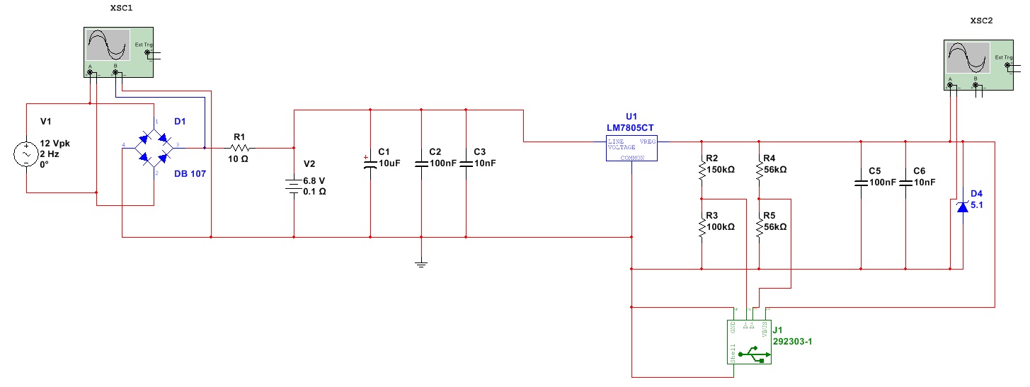
The
next circuit is the rectifier and regulator, we can see them the signal
of the output of the regulator connected to USB port type A.
In
this part I should test if the level of the current that the regulator
sends is enough to charge a cell phone. If it is not, I should redisign
the part of rectifier and battery. I finally add to the circuit a microcontroller as is shown.
The purpose microcontroller is to sense the voltage level of the battery and turn on an LED when fully charged.