Week14Mechanical design, machine design
José J. Lazarte R.

(student) assignment
   do the mechanical design for your final project ...

In my final project is required to perform the design of the mechanical part that will transform the kinetic energy contained in the act of walking into mechanical energy applied to a lever movement.
Such movement will transmit the action lever to an electric generator.  To do this I will require three parts, the lever holder, lever and a gear.
Then we make the modeling of the support lever which consists of a platform that will be mounted the other two mechanical parts and it will support the entire structure.
I planned to use as a material plywood of
15 mm. I has been thought to implement it into two parts.

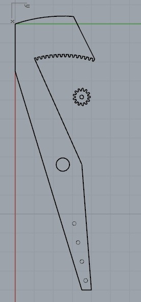
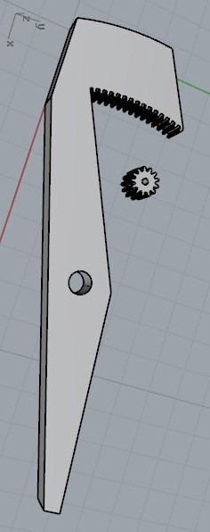
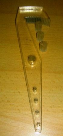
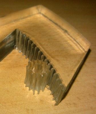
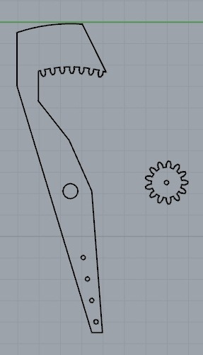
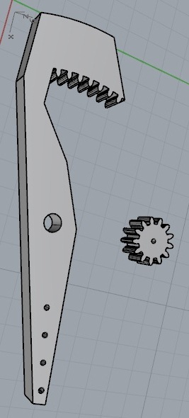
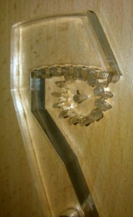
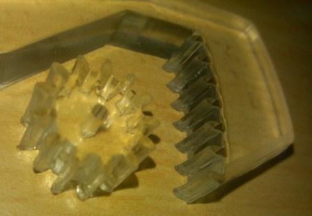
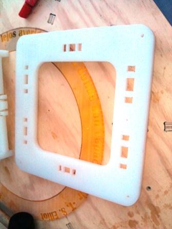
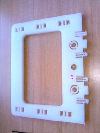
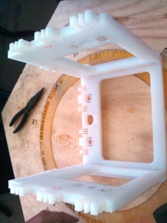
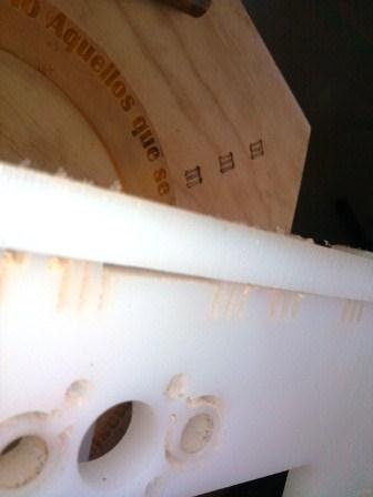
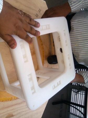
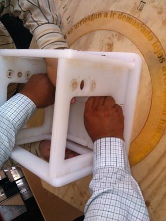
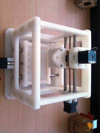
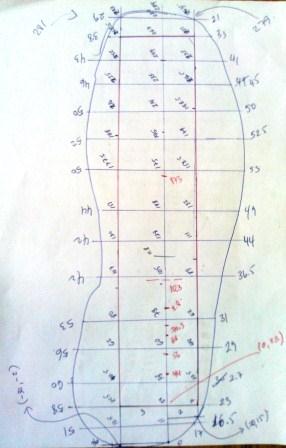
In the image shown is the template from which the data were taken ...

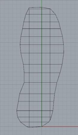
...to draw the template model using Rhinoceros software.

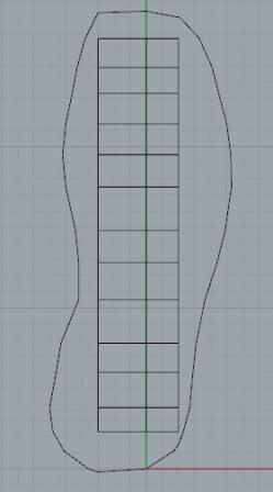
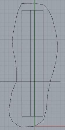
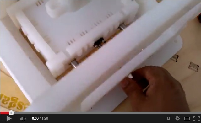
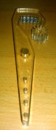
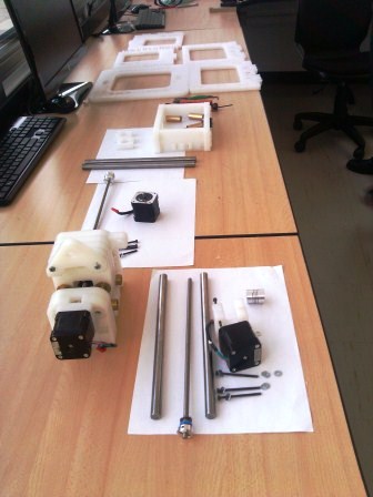
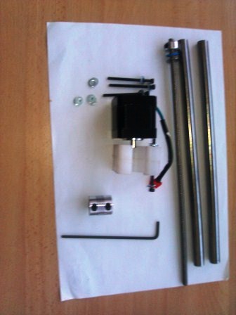
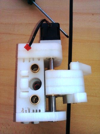
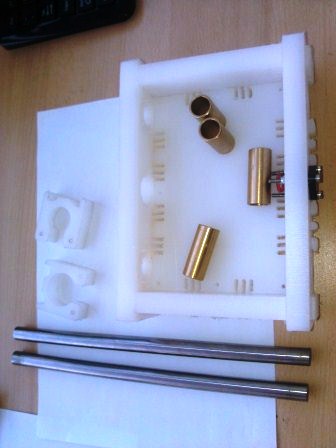
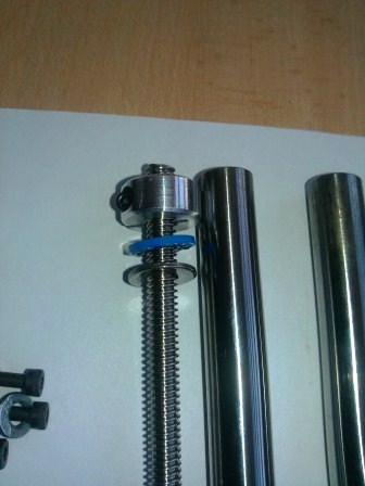
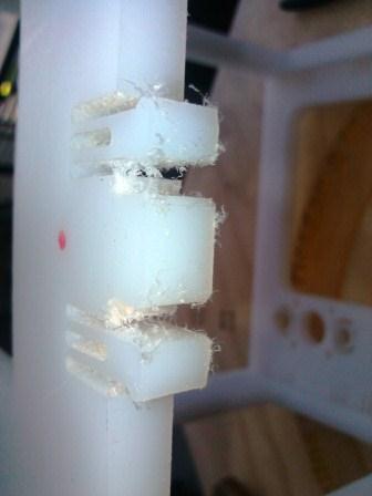
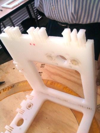
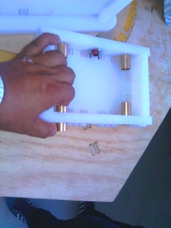
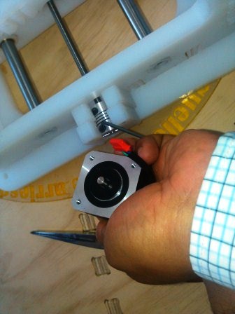
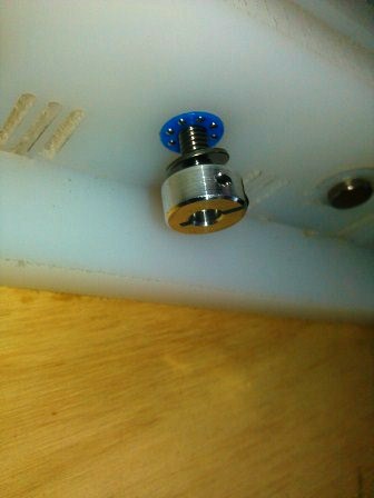
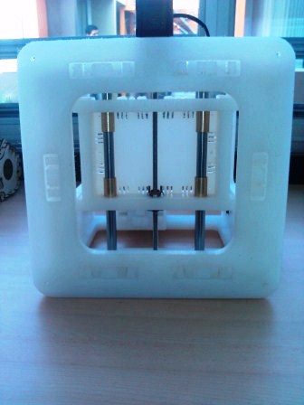
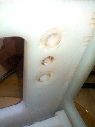
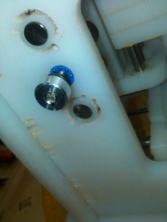
The bottom where the lever shaft, generator and slot planca will fit...

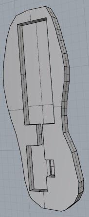
Top that will contain support for the springs ...
Then the design of the gear lever was held for a number of teeth  and  initially consider it too big and in the size of these was too small. The difficulty of it is in the process of which the laser court had not the precision for acrylic (I use a 1 mm. of thickness) this is shown in the following figures.
For that reason the gear teeth and the size is decreased, which improved torque and rotation in the movement increased. But to do so, I had to modify the shape of the gear lever and resizing, this is shown in the following figures.
With that I already have structured the mechanics that will allow me to install the generator.


(instructor) assignment
   design or modify a machine, making as many of the components as possible
   document the group project and your individual contribution
   make the passive parts and operate it manually
After the instructors performed the  modification of a drill machine of  3 degrees of freedom, they gave us the parts and as a group project, we must make the assembly of the structure and axes;so we separate in groups for us all to hab the experience to assembly the equipment.
I had the opportunity to perform the assembly of the structure and two-axis (x-axis and y-axis).
The first part is the assembly of the structure that will hold up to the machine and platform bottom axis (x axis).

The second part is the set up of the axes using copper parts, plain bearings, flexible couplings.
Finally the machine already assembled with motors coupled proved manually move the axes shown.

Video 1