Assignment
This week's assignment is to design and build an
output device. My choice was to design and build a board that
would provide a regulated output voltage and also include a MosFet
to switch the voltage on and off with a separate 5V signal from a
microcontroller.
The circuit
The circuit includes:
- 9V battery with 2 wire connection
- 3 pin input header, 2 pins for 9V battery, 1
pin for 5V microcontroller input
- NMosfet
- Voltage regulator
- 1 pullup resistor
- 2 capacitors
- 2 pin output header
Schematic and Layout
Eagle was used to create the circuit and complete
the layout.
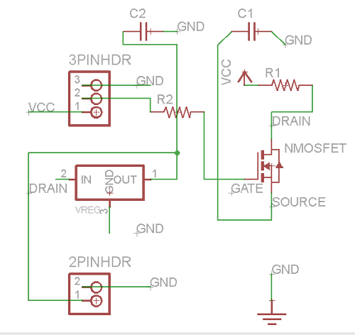
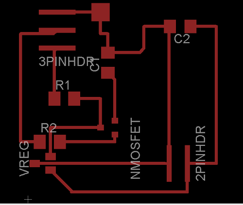
Eagle Schematics and Layout
Fabrication and Assembly
The board was fabricated on the Modela milling
machine.
Fabrication Issues
An error was made on the outline milling profile
which removed one of the traces. This was addressed with a jumper
wire as shown in the photo below.
There was a short on the trace running under the zero ohm resistor
(R2). This was addressed by removing the copper with an exacto
knife.
There was a short on the trace running under the voltage
regulator. This was addressed by removing the copper with an
exacto knife.
Testing and Debug
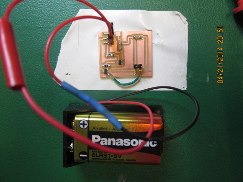
Power board and battery
The board was connected to a 9V battery as shown in
the photo. The power cable was assembled by stripping the wires
and soldering the wires to single pin headers, then insulating the
soldered connection with tape.
The 5V switching signal was simulated on pin 2 of the input header
using the 5V output of an Arduino board. Initial testing indicated
there was no output voltage on the 2 pin header.