This week's summary
This week's exercise was to modify an existing board design and
then to fabricate and assemble the board.
The base board design is the Fab Lab Echo Board. The additions are
a Button, a LED and the associated components.
Tools and References
Eagle Software 6.5.0 was the primary tool used for
the design. A version of this is available as a free download.
Eagle includes many component libraries with the download, but
additional components need to be downloaded for this specific
design.
The "base design" schematics (.sch) and board (.brd) files were
imported into Eagle (from the Fab Academy archives).
Design Notes
Parts were added in the schematics view using the
"Add" button on the left hand toolbar.
Connections were made in the schematics using a combination of
mouse clicks and NET names (example of NET names is "LED" net
highlighted in schematics below).
As connections were made, I switched back and forth to the board
view to ensure traces were being created.
The parts and traces appeared on the bottom left of the board
view (off the board).
Switching to board view, the parts were positioned inside the
board outline.
Autoroute was run (Tools, Autorouter) as a preliminary routing.
A number of traces were cleaned up using the Ripup and Route
buttons on the left hand toolbar.
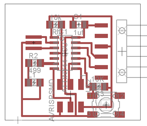
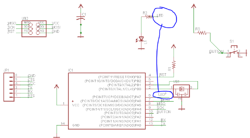
Board layout (upper) and schematics (lower)
Design Checks
DRC was run with clearances set at 16 mils on Tools, DRC,
Clearance tab as shown below (to allow clearance for 1/64 inch end
mill on Modela).
After a couple of iterations and trace adjustments, the DRC came
back with zero errors.
As a check, DRC was run again at 25 mils to ensure it was
operating properly (and provided errors as expected).
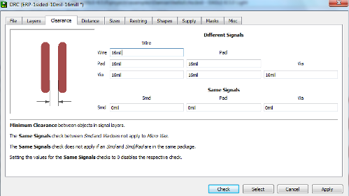
Tools/DRC/Clearance tab
ERC was run and came back with the errors shown
below.
After review, none of these errors were considered significant.
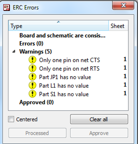
ERC Results
Fabrication Notes
The board was fabricated using the Modela milling
machine.
Traces were cut with a 1/64 inch diameter bit.
The traces.png file was loaded then the x and y start positions
were determined visually based on the material position.
Important Note: You must take note of x,y position now - you
will need it later for board outline cut.
The tool was zeroed in the Z axis by jogging close to the surface
then loosening the bit, dropping to surface and tightening.
The next steps were Make Path, Make rml and Send It which starts
the cutting process.
The outline was cut using a 1/32 inch diameter bit and the same
sequence above.
The x,y start position used for cutting the outline is
the same as that used for the traces.
Assembly Notes
Order of components - Push button, ATTiny,
Resonator, Discrete components, Headers.
In hindsight it may have been better to solder the headers before
the discretes.
Tape the board to the workbench using double sided tape.
The resonator has wrap around contacts (not leads) and is
difficult to solder. Ensure solder is applied on both sides of
leads.
For the 6 pin header, the material available was a straight
through header.
We bent the shorter side of the leads at an approx 30 degree angle
and soldered them to the board.
The connector housing serves as a stabilizer during soldering and
also as an insulator to avoid shorts.
The Outcome
The board did not work on first attempt and we were not able to
download the program.
For debug, we checked continuity on a number of pins around the
microcontroller - no issues found.
At that point the resonator was checked, and the
soldering/alignment did appear suspect.
Removal and resoldering of the resonator did resolve the problem
and we were able to download the program.
However, the LED did not blink when we ran the Arduino "Blink"
program.
It was discovered that the LED component was reversed - rotating
the device resolved the issue.
After these rounds of troubleshooting and repairs the board
worked as designed.